Organic light emitting display device

a technology of light-emitting display device and organic material, which is applied in the direction of lighting and heating apparatus, instruments, casings/cabinets/drawer details, etc., can solve the problems of easy damage to the oled device, deterioration of the productivity of the oled device, and difficulty in separating the sealing member and the bottom cover from each other, so as to facilitate the combination and separation, prevent misalignment, and enhance productivity

Active Publication Date: 2014-03-27
LG DISPLAY CO LTD
View PDF10 Cites 16 Cited by
  • Summary
  • Abstract
  • Description
  • Claims
  • Application Information

AI Technical Summary

Benefits of technology

[0009]The embodiments are to provide an OLED device which can be easy to combine and separate an OLED panel and a bottom cover with and from each other.
[0010]Also, the embodiments are to provide an OLED device which is adapted to enhance productivity.
[0011]Furthermore, the embodiments are to provide an OLED device which is adapted to prevent misalignment.

Problems solved by technology

If a fault is generated in the OLED panel and so on during a manufacturing process, it is difficult to separate a sealing member and the bottom cover from each other due to the strong adhesive force of the double-sided tape.
As such, the OLED device can be easily damaged.
Therefore, the productivity of the OLED device can deteriorate.
Furthermore, there is a problem often generating misalignment between the OLED panel and the bottom cover in a curved type OLED device due to the double-sided tape.

Method used


Image

  • Organic light emitting display device
  • Organic light emitting display device
  • Organic light emitting display device

Examples


first embodiment

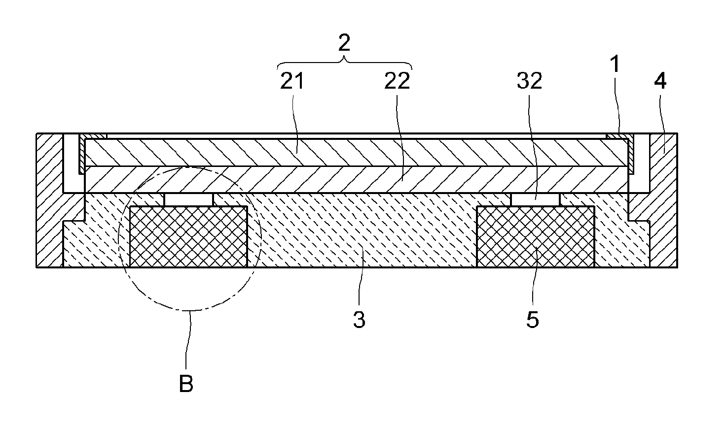
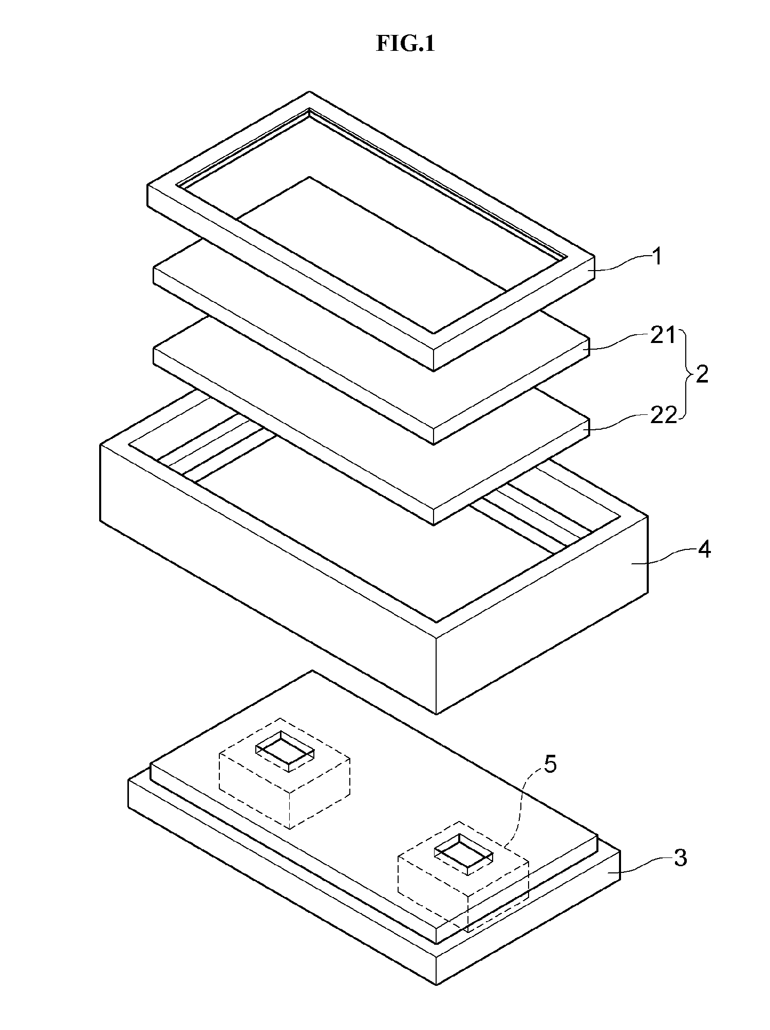
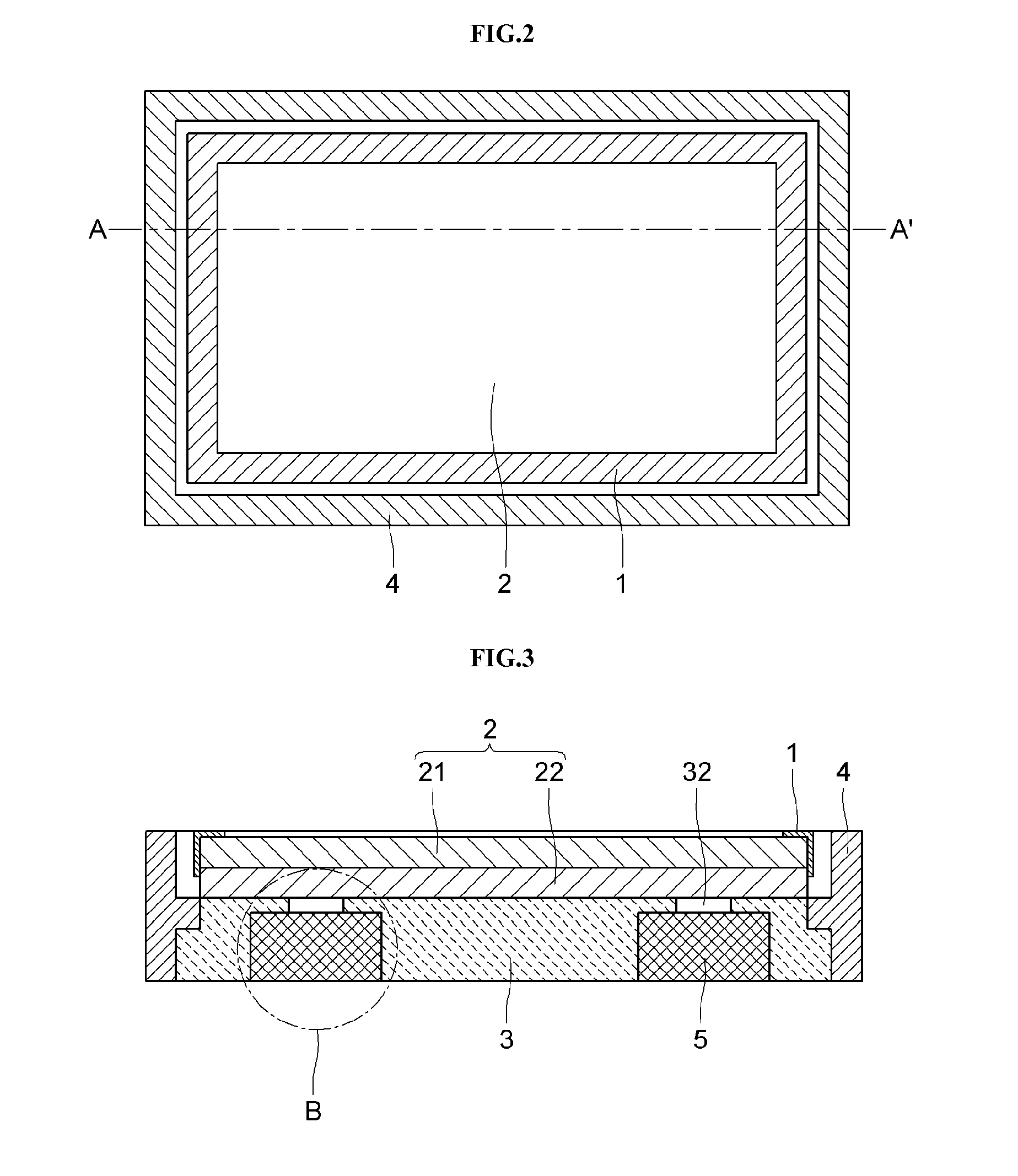
[0037]FIG. 1 is a disassembled perspective view showing an OLED device according to an embodiment of the present disclosure. FIG. 2 is a planar view showing the OLED device of FIG. 1. FIG. 3 is a cross-sectional view showing an OLED device, which is taken along a line A-A′ in FIG. 2, according to the present disclosure.

[0038]Referring to FIGS. 1 through 3, the OLED device according to a first embodiment of the present disclosure can include an upper cover 1, an OLED panel 2, a bottom cover 3 and a side cover 4.

[0039]The OLED panel 2 can be used to display images. The OLED panel 2 can include a thin film transistor substrate 21 and a sealing member 22.

[0040]The thin film transistor substrate 21 can include a plurality of pixels which are defined by a plurality of gate lines and a plurality of data lines. Each of the pixels can include a thin film transistor (not shown) and an organic light emission diode (not shown).

[0041]The sealing member 22 can be used to protect a variety of line...

second embodiment

[0069]FIG. 10 is a cross-sectional view showing an OLED device, which is taken along a line A-A′ in FIG. 2, according to the present disclosure.

[0070]The OLED device of the second embodiment is the same as that of the first embodiment with the exception of magnet covers 35. The components of the second embodiment having the same function and shape as those of the first embodiment will be referred to by the same reference numbers and names. Also, the description of the second embodiment overlapping with the first embodiment will be omitted.

[0071]Referring to FIG. 10, the magnet covers 35 each covering the first holes 31 can be arranged on the lower surface of the bottom cover 3. The magnet cover 35 can serve to stop up the first hole 31 into which the magnet 5 is inserted. The magnet cover 35 can be formed in such a manner as to be separated from the magnet 5. The magnet 5 can be fastened to magnet cover 35 by means of one of a screw and an adhesive material. Alternatively, the magne...

third embodiment

[0076]FIG. 12 is a cross-sectional view showing an OLED device, which is taken along a line A-A′ in FIG. 2, according to the present disclosure.

[0077]The OLED device of the third embodiment is the same as that of the first embodiment with the exception of second magnets 6. The components of the third embodiment having the same function and shape as those of the first embodiment will be referred to by the same reference numbers and names. Also, the description of the third embodiment overlapping with the first embodiment will be omitted.

[0078]As shown in FIG. 12, first magnets 5 can be inserted into the inside of the bottom cover 3. Also, a plurality of second magnets 6 can be arranged on the upper surface of the bottom cover 3. The second magnet 6 can be disposed at a position of the upper surface of the bottom cover 3 opposite to the first magnet 5. The second magnet 6 can be attached to the upper surface of the bottom cover 3 by an attractive power which is derived from the magnet...


PUM


Abstract

An organic light emitting display device is disclosed which includes a magnet inserted into a bottom cover. The magnet is used to combine an organic light emitting display panel with a support means which is used to support the organic light emitting display panel and includes an upper cover, the bottom cover and a side cover. A sealing member included in the organic light emitting display panel is fastened to the bottom cover by a magnetic force of the magnet. As such, it is easy to separate the organic light emitting display panel and the support means from each other when a fault is generated in any component. In accordance therewith, the manufacturing process can be simplified and the faulty component can be easily replaced with a normal component. As a result, the manufacturing costs of the organic light emitting display device can be reduced.

Description

[0001]The present application claims priority under 35 U.S.C. §119(a) of Korean Patent Application Nos. 10-2012-0106074 filed on Sep. 24, 2012, and 10-2013-0111762 filed on Sep. 17, 2013, which is hereby incorporated by reference in its entirety.BACKGROUND[0002]1. Field of the Disclosure[0003]The present application relates to an organic light emitting display device.[0004]2. Description of the Related Art[0005]Nowadays, a variety of display devices are being developed. The display devices include liquid crystal display (LCD) devices, plasma display panel devices, organic light emitting display (OLED) device, electroluminescent display devices and so on.[0006]Among these display devices, OLED devices have the features of lower power consumption, wider viewing angle, lighter weight and higher brightness compared to LCD devices. As such, the OLED device is considered to be next generation display devices.[0007]The OLED device allows an OLED panel and a bottom cover to be combined with...

Claims


Application Information

Patent Timeline
Patent Type & Authority Applications(United States)
IPC IPC(8): H05K5/03
CPCH05K5/03G06F1/1601H10K50/8423H10K50/84G09G3/3208
Inventor JUN, GI HYON
Owner LG DISPLAY CO LTD
Why Eureka
Try Eureka