Pluggable system and optical transceiver applicable to pluggable system

a technology of pluggable systems and optical transceivers, applied in the direction of optical elements, coupling device connections, instruments, etc., can solve the problems of weakened pulling force caused by gaskets

Inactive Publication Date: 2014-03-27
SUMITOMO ELECTRIC IND LTD
View PDF9 Cites 5 Cited by
  • Summary
  • Abstract
  • Description
  • Claims
  • Application Information

AI Technical Summary

Benefits of technology

[0008]The periodic structure formed in the rear of the housing may be a plurality of hollows or a plurality of projections. The rear of the housing may come in contact with the gasket only in restricted portions except for the hollows, or portions of the projections. Moreover, the width of each of the hollows, or the pitch to the neighbor projections are set to be shorter than a quarter wavelength of a signal transmitted between the electrical plug of the optical transceiver and the host connector; accordingly, EMI radiations with wavelengths thereof longer than the width or the pitch above may be prevented from leaking from a rear portion of the optical transceiver.
[0012]The periodic structure may be a plurality of hollows or projections. The rear of the housing may come in contact with the host connector only in restricted portions except for the hollows, or only in the projections. The width of each of the hollows, or the pitch between neighbors of the projections may be set shorter than a quarter wavelength of a signal transmitted through the electrical plug, which may prevent EMI radiations from leaking from the electrical plug.

Problems solved by technology

In the pluggable system according to an embodiment, when the optical transceiver is set on the host system, namely, the electrical plug is mated with the host connector as deforming the gasket in the groove, the repulsing force caused by the gasket may be weakened because only limited portions of the rear may come in contact with the gasket.

Method used


Image

  • Pluggable system and optical transceiver applicable to pluggable system
  • Pluggable system and optical transceiver applicable to pluggable system
  • Pluggable system and optical transceiver applicable to pluggable system

Examples


first embodiment

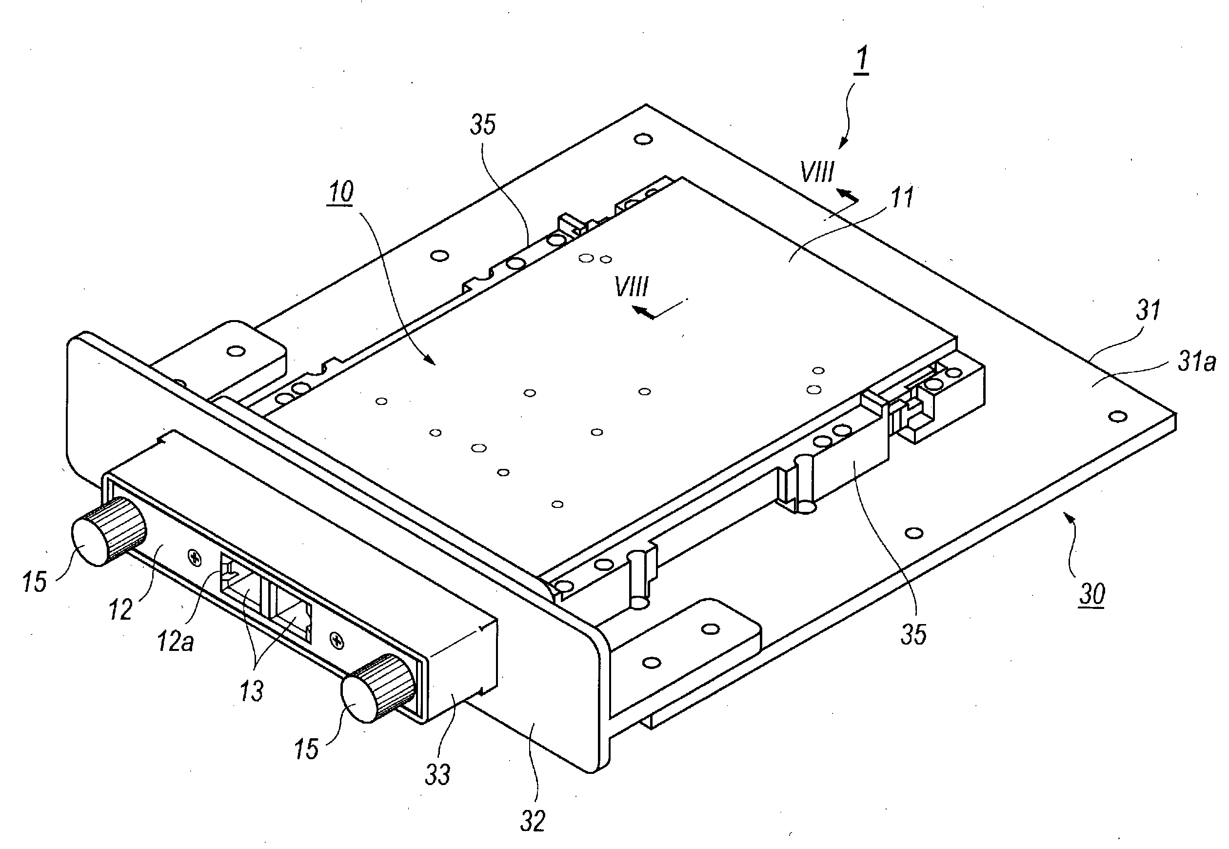
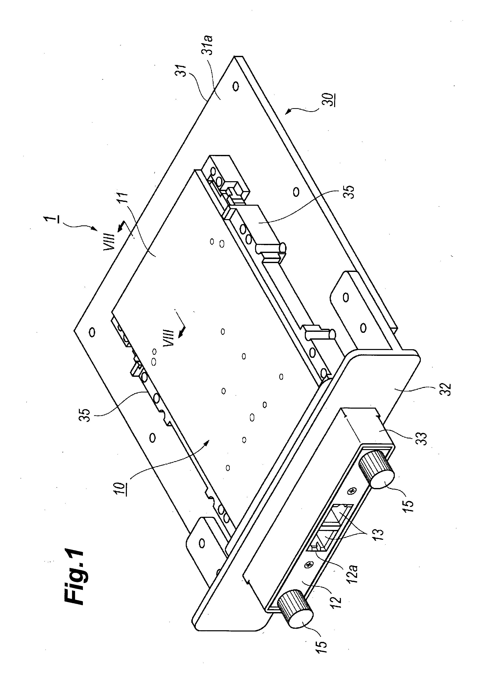
[0036]FIG. 1 is a perspective view of a pluggable system 1 according to the first embodiment of the present invention, where the pluggable system includes an optical transceiver 10 and the host system 30. The optical transceiver 10 has a type of, what is called, the pluggable optical transceiver following the standard of the CFP.

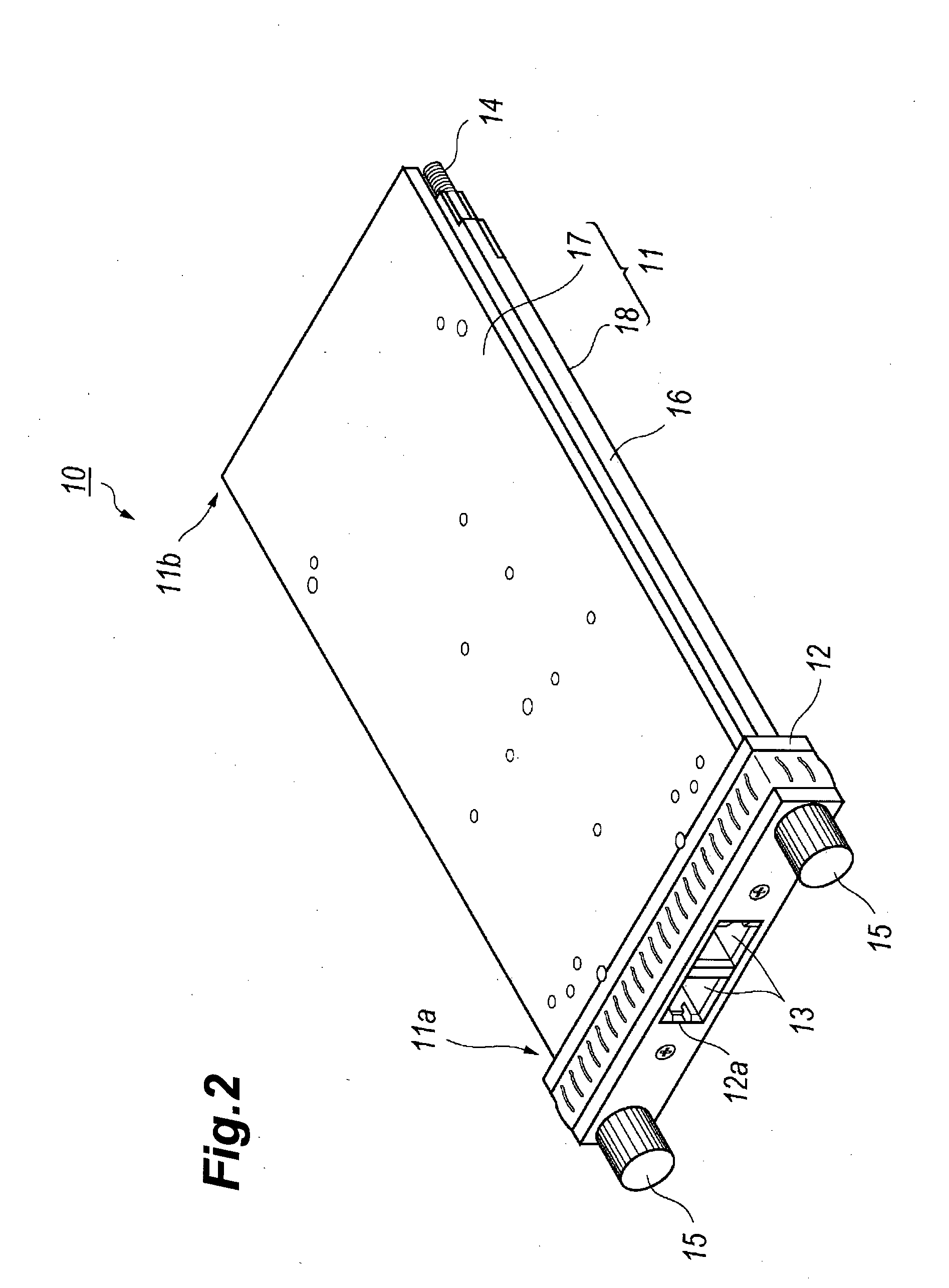
[0037]FIG. 2 is a perspective view of the optical transceiver 10 viewed from the front top; while, FIG. 3 shows the optical transceiver 10 viewed from the rear bottom. The optical transceiver 10, as illustrated in FIGS. 2 and 3, includes a housing 11 and a front cover 12 attached to the front end 11a of the housing 10. The housing 11 may be made of, for instance, aluminum or zinc from viewpoints of the heat dissipation and the castability. The description presented below assumes, only by the explanation sake, that the front is a side where the front cover 12 is assembled; while, the rear is the other side where the electrical plug 23 is disposed. The front c...

second embodiment

[0051]Next, a pluggable system including an optical transceiver and a host connector cover according to the second embodiment of the invention will be described. FIG. 13 shows the pluggable system of the second embodiment where the pluggable system 1A includes an optical transceiver 10A and the host system 30A.

[0052]FIG. 14 is a perspective view concentrating on a rear portion of the optical transceiver 10A that provides, instead of the rear 22 of the former embodiment, the rear 22A. Other arrangements of the optical transceiver 10A are the same as those of the aforementioned optical transceiver 10. The rear 22A is substantially flat, namely, the rear 22A of the present embodiment may be distinguishable from the former embodiment that the rear 22A provides no hollows 11A and projections A21.

[0053]FIG. 15 is a perspective view showing the host system 30A shown in FIG. 13. The host system 30A is distinguishable from the aforementioned host system 30 in that the host system 30A of the ...


PUM


Abstract

An optical transceiver and a pluggable system to enhance the reliability of the communication between the optical transceiver and the host system are disclosed. The rear of the housing of the transceiver provides a periodic structure, a plurality of hollows or a plurality of projections, arranged along the gasket provided in the host connector. Only portions of the periodic structure come in contact with the gasket, and the repulsive force caused by the gasket is consequently weakened to enhance the reliability of the mating of the plug in the optical transceiver with the host connector. The width of the hollows, or the pitch of the projections is set to be shorter than a quarter wavelength of a signal transmitted between the transceiver and the host system to reduce the EMI radiation leaking from the end of the transceiver.

Description

TECHNICAL FIELD [0001]Embodiments of the present invention relates to a pluggable system for an optical transceiver that includes a pluggable optical transceiver and a host connector cover of a host connector.BACKGROUND ART[0002]Various pluggable systems for an optical transceiver and a host connector have been disclosed in prior arts. For instance, the United State Patent, the U.S. Pat. No. 7,710,734, has disclosed a platform including a pluggable optoelectronic module and a host system installing the module. The optoelectronic module includes a circuit board mounting optical and electrical components thereon, a housing for enclosing the board therein and an electrical plug electrically connected with the board and extruding from a rear of the housing. The host system includes a host connector to be mated with the electrical plug and a host connector cover for covering the host connector. The host connector cover provides an opening in the front thereof through which the electrical...

Claims


Application Information

Patent Timeline
Patent Type & Authority Applications(United States)
IPC IPC(8): H01R13/52H01R13/658H04B10/2507H04B10/40H04B10/43H04B10/50H04B10/60
CPCH01R13/658H01R13/5219G02B6/4261G02B6/4277G02B6/4284
Inventor OKI, KAZUSHIGE
Owner SUMITOMO ELECTRIC IND LTD
Why Eureka
Try Eureka