

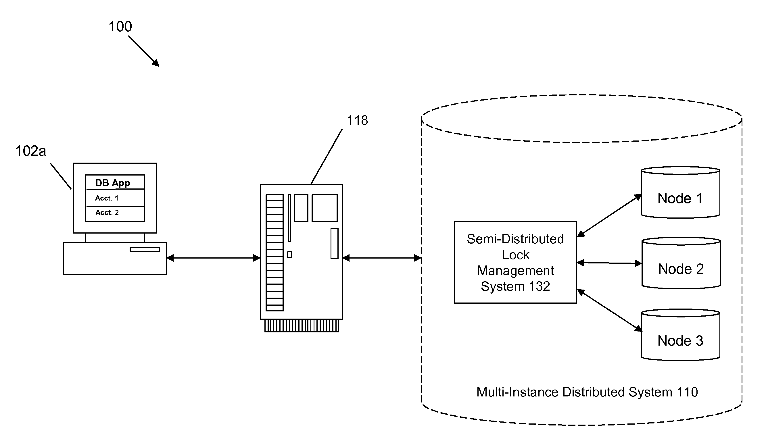
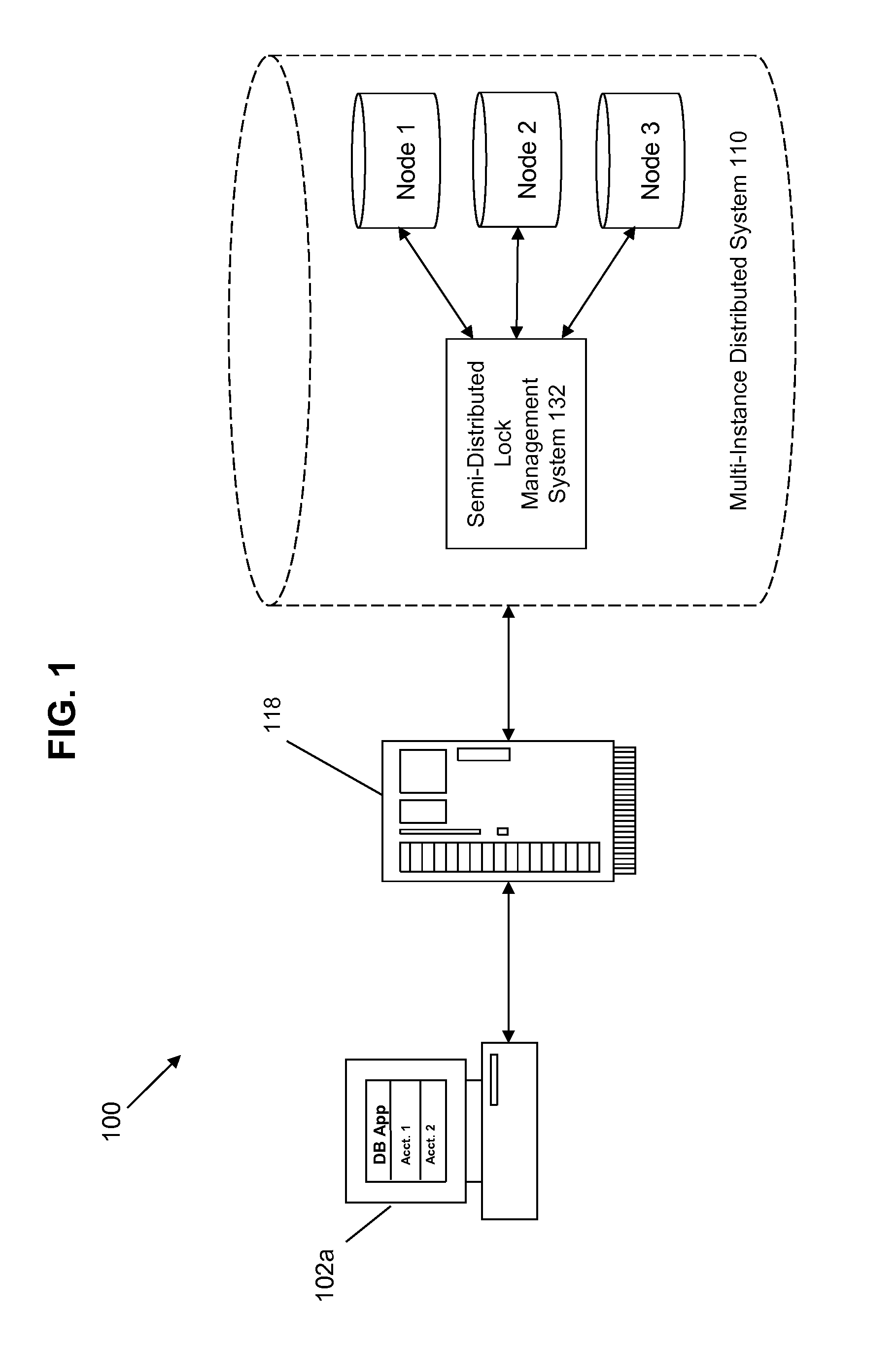
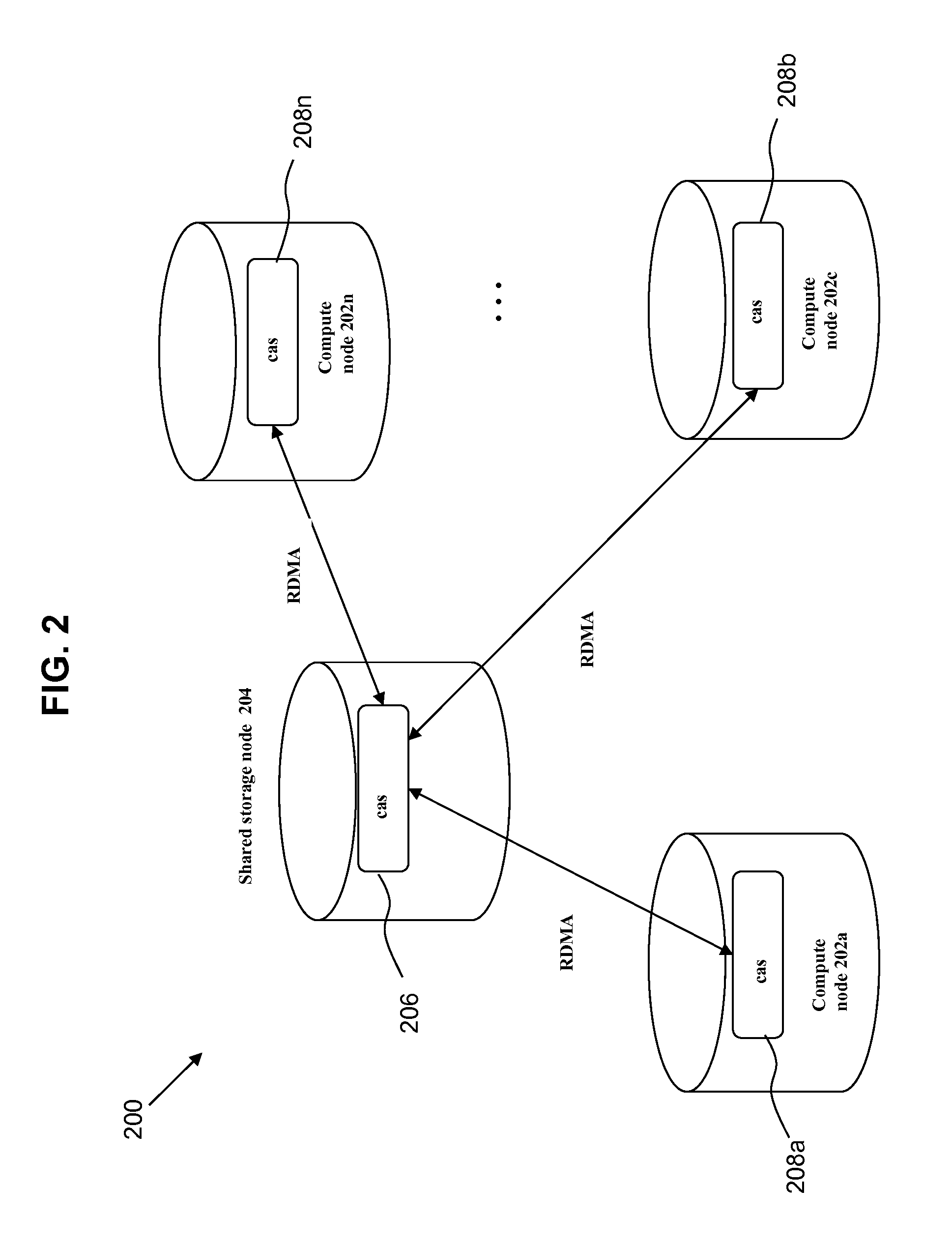
Methods and apparatus for implementing semi-distributed lock management
a semi-distributed and lock technology, applied in the field of lock management, can solve the problems of clm approach having single point of failure, clm approach posing the risk of single point failure, centralized approach lacks the flexibility and autonomy needed by processes at each compute node in modern multi-instance database system, etc., to achieve higher flexibility and autonomy, simplify complicated deadlock detection process, and improve system performan
- Summary
- Abstract
- Description
- Claims
- Application Information
AI Technical Summary
Benefits of technology
Problems solved by technology
Method used
Image

Examples
Embodiment Construction
[0020]A method, system, and computer program product are provided for implementing semi-distributed lock management for a distributed processing system. Various embodiments are described hereinafter with reference to the figures. It should be noted that the figures are not drawn to scale and that the elements of similar structures or functions are represented by like reference numerals throughout the figures. It should also be noted that the figures are only intended to facilitate the description of the embodiments. They are not intended as an exhaustive description of the invention or as a limitation on the scope of the invention. In addition, an illustrated embodiment need not have all the aspects or advantages shown. An aspect or an advantage described in conjunction with a particular embodiment is not necessarily limited to that embodiment and can be practiced in any other embodiments even if not so illustrated. Also, reference throughout this specification to “some embodiments”...
PUM
 Abstract
Description
Claims
Application Information