Method for manufacturing registration template

a registration template and manufacturing method technology, applied in the field of manufacturing registration templates, can solve the problems of difficult to perform precise registration, requiring restrictions on the patient's behavior, and affecting the accuracy of surgical tool positioning accuracy, so as to reduce the number of tomography operations and reduce the number of exposures to radiation by ct. , the effect of accurate alignmen

Inactive Publication Date: 2014-04-10
ONO
View PDF5 Cites 141 Cited by
  • Summary
  • Abstract
  • Description
  • Claims
  • Application Information

AI Technical Summary

Benefits of technology

[0028]The present invention is advantageous in that the surface of a patient's hard bone is subjected to registration in the navigation system, se that accurate alignment can be performed, and no burden for surgery intended for registration is imposed on the patient. Moreover, photographic data from single tomography can be utilized through template production, registration and navigation. This brings the advantage that it is not necessary, for example, to photograph images of the patient to whom markers were adhered in advance. This is also advantageous in that since the number of tomography operations is reduced, the number of exposures to radiation by CT is decreased, and the time required before surgery can be shortened markedly.
[0029]Furthermore, the operation o

Problems solved by technology

Moreover, the precision of registration directly affects the accuracy of the position of the surgical tool during navigation, and presents a very important problem in the medical navigation system.
However, the pasting of the markers is usually performed on the day before surgery, thus requiring restrictions on the patient's behaviors.
Thus, precise registration is difficult to perform.
This technology, however, is also defective in that registration on the skin surface of t

Method used


Image

  • Method for manufacturing registration template
  • Method for manufacturing registration template
  • Method for manufacturing registration template

Examples


example 1

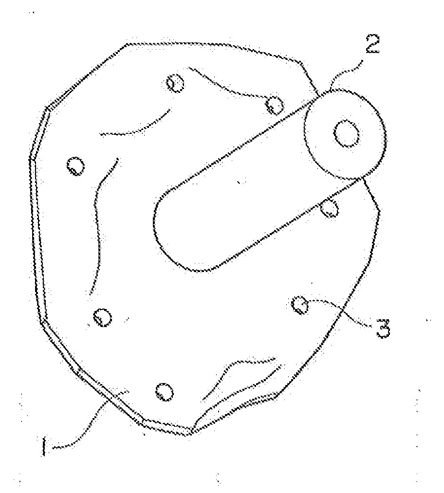
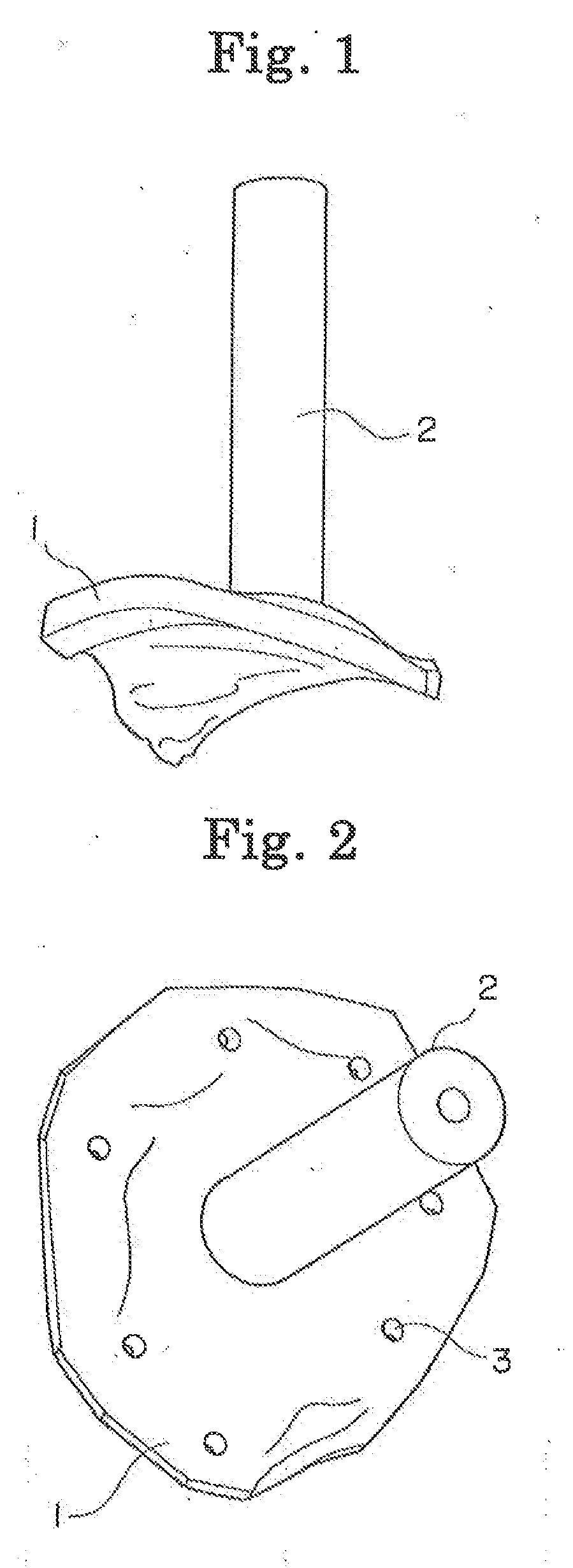
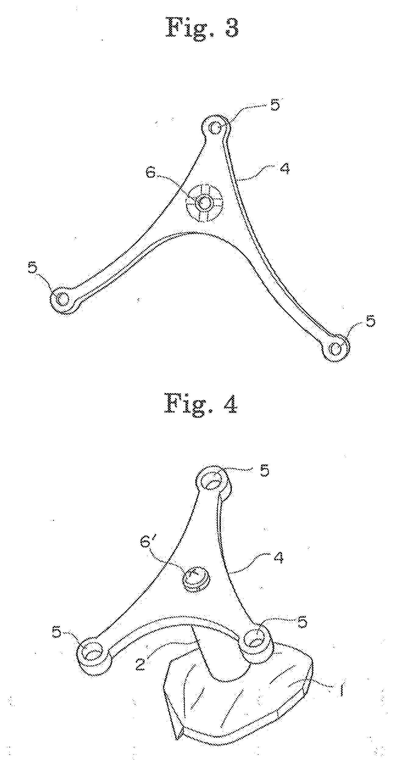
[0089]A model of a temporal site as a surgical target was produced by powder sintering, and a registration template intimately contacting the temporal site was manufactured by stereolithography,

[0090]A mixture of 70% by mass of a spherical nylon 11 powder having an average particle diameter of 58 μm and 30% by mass of glass beads having an average particle diameter of 60 μm was used as a material to be powder-sintered, and a selective laser sintering device with a 100 W carbon dioxide laser [“Vanguard-HS”, a product of 3D-Systems] was used as a shaping device. An epoxy resin (trade name TSR-829, produced by CMET Inc.) was used as a stereolithographic material, and the shaping device (“SOLIFORM600EP”, produced by CMET Inc.) was used.

[0091]Based on data from X-ray computed tomography of a bone at a temporal site in a child, data on the temporal site and a registration template were created. To the data on the template, data on the positions and dimensions of eight guide holes were add...


PUM

PropertyMeasurementUnit
Shapeaaaaaaaaaa
Transparencyaaaaaaaaaa

Abstract

A method for manufacturing a registration template for use in medical navigation system-guided surgery, comprising: producing a registration template having a surface, which precisely surface-bonds to a surface of a bone at a surgical target site of a patient, and having three or more registration points, from stereoscopic surface data ensuring precise surface bonding to the surface of the bone at the surgical target site of the patient, based on stereoscopic surface data created from tomography information on the bone of the surgical target site of the patient; and providing a pedestal (4) for mounting optical tracking balls (7), which are used for three-dimensional position detection for a medical navigation system, at the center of the registration points. By using the template having curves surfaces which three-dimensionally precisely and intimately contact the bone surface of the patient, high-precision registration can be performed, and an operator's man-hours immediately before surgery in an operating room can be reduced to shorten the surgery time.

Description

TECHNICAL FIELD[0001]This invention relates to a method for manufacturing a registration template in a medical navigation system. More specifically, the present invention relates to a method for manufacturing a registration template which has curved surfaces conforming precisely to the curved surfaces or the like of a bone at a target site for surgery (may be called a surgical target site) in a patient. In performing surgery, the method involves determining a position at which the curved surfaces of the registration template closely contact and fit into the site of surgery in the patient fixed to an operating table; prestoring in the navigation system the relative coordinates of three or more registration points provided in the registration template and balls for a three-dimensional position detecting light reflector (may be referred to hereinafter as an optical tracking antenna in the present invention), which is mounted on the template, at the position of the close contact and fit...

Claims


Application Information

Patent Timeline
IPC IPC(8): A61B19/00
CPCA61B19/201A61B19/5212A61B19/5244A61B90/39A61B2090/3983A61B90/11Y10T29/49
Inventor MATSUMOTO, NOZOMUONO, HIDENORISUGIYAMA, HISAYUKI
Owner ONO
Why Eureka
Try Eureka