Multi-Capture Mode Wave Energy Converter With Submergible Float

Inactive Publication Date: 2014-04-10
ROHRER TECH
View PDF9 Cites 19 Cited by
  • Summary
  • Abstract
  • Description
  • Claims
  • Application Information

AI Technical Summary

Problems solved by technology

Water's relatively high density (over 800 times greater than air) largely accounts for the higher energy density of waves, but also increases the challenges of severe sea-state survivability for WECs.
This makes the WECs both expensive and unresponsive (inefficient) during more normal sea-states.
Circular section and other narrow-width buoys must square their sectional area and cube their volume (exponentially increasing their weight and cost) to intercept and access the energy from additional oncoming wave fronts.
Vertically-heaving buoys can only capture the heave or potential energy component that likely cannot exceed 50% of total wave energy.
If the

Method used


Image

  • Multi-Capture Mode Wave Energy Converter With Submergible Float
  • Multi-Capture Mode Wave Energy Converter With Submergible Float
  • Multi-Capture Mode Wave Energy Converter With Submergible Float

Examples


Embodiment Construction

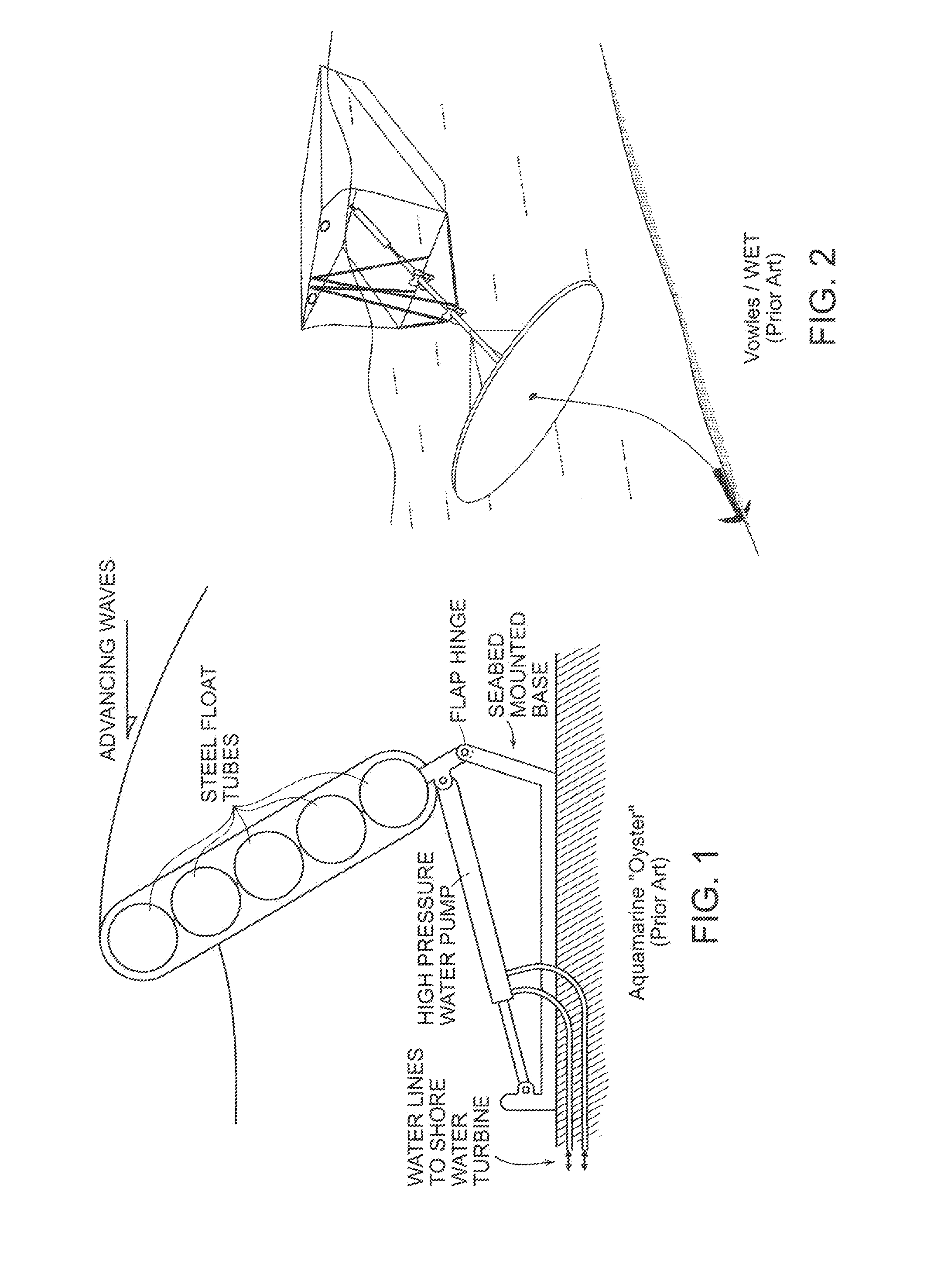
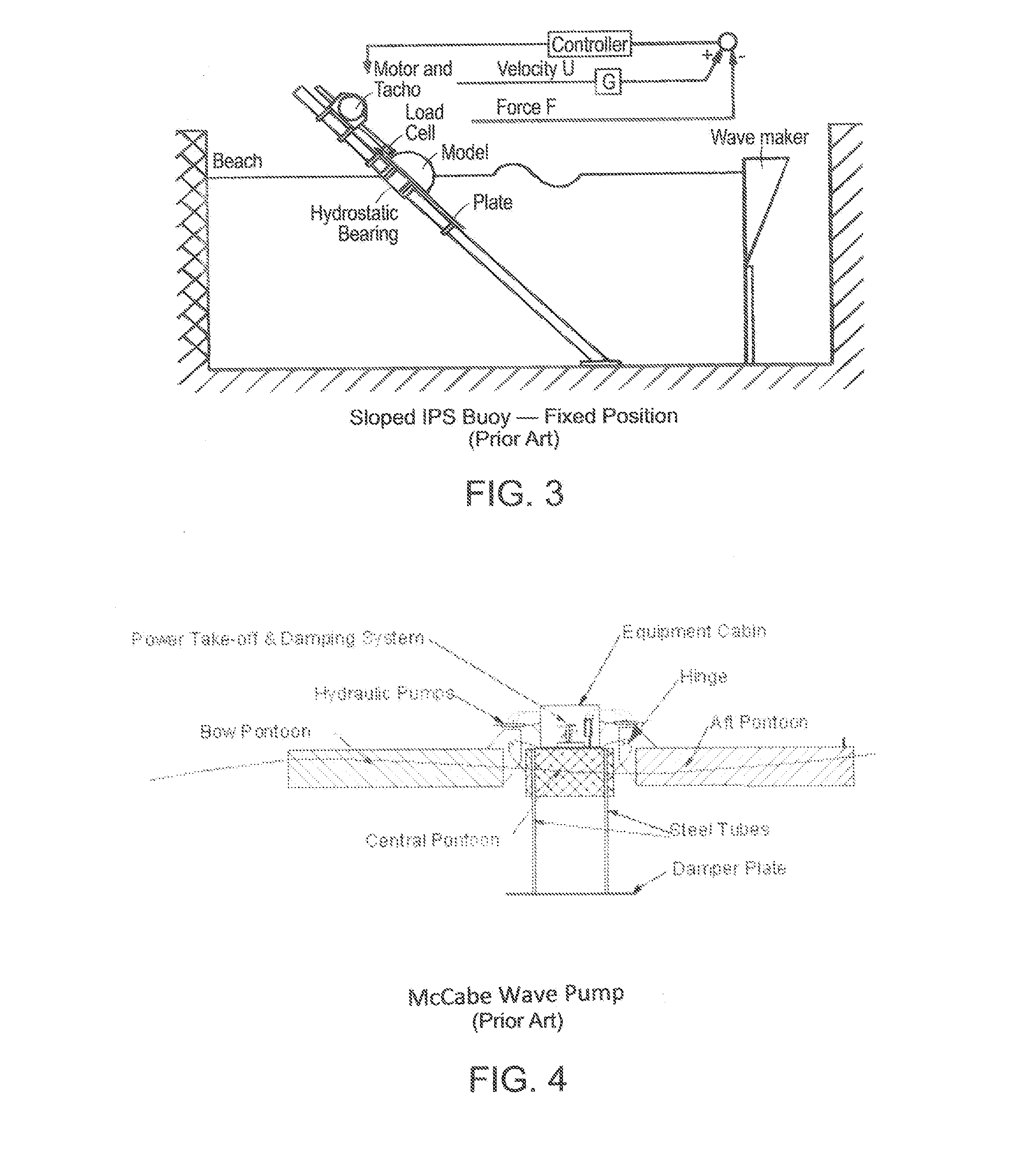
[0045]The features and limitations of the Related Art WECs of FIG. 1 through FIG. 4, inclusive, are previously described and discussed in the previous Distinguishing Features over the Prior Art section.

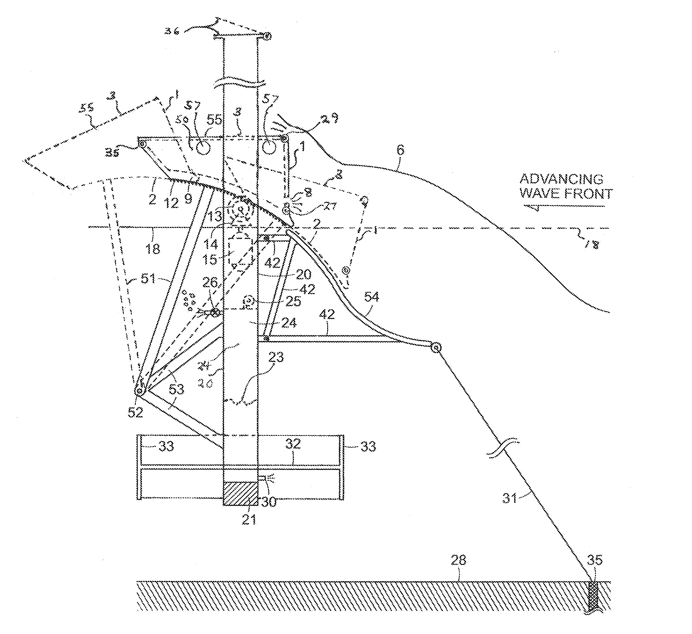
[0046]Referring to FIG. 5, an embodiment of the disclosure is shown wherein one or more relatively lightweight floating elongated buoyant float(s) or barrier(s) having a wave front facing and impacting forward face 1 which may be buoyant or non-buoyant, concave, convex, flat (as shown) and sloping upwardly, or generally vertical and outwardly and being a rigid (shown) or a hinged panel (shown) or a flexible wave impacting front wall (not shown), with the float having a relatively flat and upward and rearward sloped bottom wall 2. A cavity in the float(s) 4 created by the forward wall 1 and a bottom wall 3 can have an open upward facing cavity (not shown), be solid, or hollow (not shown), or have a top cover plate 55. This top or “splash cover”55, prevents excessive seawater 6 from imp...


PUM


Abstract

An ocean wave energy converter (WEC) uses one or more buoyant elongated float(s) mechanically linked to a motion-stabilized, controlled-submergence depth frame by either swing or lever arms or down-sloping tracks defining and orienting the motion of the floats relative to the frame to capture both heave and surge wave energy forces. The submerged depth of the frame and attached float(s) is adjusted for optimal wave energy capture or submerged sufficiently to fully submerge the float(s) during severe sea conditions. The elongated float's compliant wave-impacting forward wall combined with total submergence during severe sea states allows the elongated float(s) to self-orient parallel to oncoming wave fronts to intercept and capture maximum wave energy per unit of WEC volume, weight and cost.

Description

RELATED U.S. APPLICATION DATA[0001]Continuation-in-part of application Ser. No. 13 / 506,680 filed on May 8, 2012 (and PCT / US2012 / 053590) which is a continuation-in-part of application Ser. No. 13 / 199,607 filed on Sep. 2, 2011.[0002]Provisional Application No. 61 / 628,732 filed on Nov. 5, 2011.CROSS-REFERENCE TO RELATED APPLICATIONS[0003]This is a continuation-in-part of U.S. application Ser. No. 13 / 506,680, filed May 8, 2012 (corresponding to PCT / US2012 / 053590), which is a continuation-in-part of U.S. application Ser. No. 13 / 199,607, filed Sep. 2, 2011, the contents all of which are incorporated in their entirety herein by reference.FIELD OF THE DISCLOSURE[0004]This disclosure relates to devices for producing electrical power, pressurized water, or other useful work from surface waves on a body of water.[0005]More particularly, this disclosure relates to wave energy converters (or “WECs”) of the wave terminator or wave energy absorption barrier type wherein one or more elongated wave ...

Claims


Application Information

Patent Timeline
IPC IPC(8): F03B13/14
CPCF03B13/14F03B13/182F03B13/186F05B2270/18Y02P60/12Y02E10/30
Inventor ROHRER, JOHN W.
Owner ROHRER TECH
Why Eureka
Try Eureka