Image encoding apparatus and image encoding method

Inactive Publication Date: 2014-04-17
CANON KK
View PDF9 Cites 15 Cited by
  • Summary
  • Abstract
  • Description
  • Claims
  • Application Information

AI Technical Summary

Benefits of technology

The patent aims to reduce the power consumption of an image encoding apparatus.

Problems solved by technology

In the image encoding apparatus that codes a video in real time, however, if a prediction mode and a prediction block size are searched for comprehensively among a number of candidates, the power consumption increases.
In addition, when the above-described processing of extracting image characteristic information in the image encoding apparatus, the power consumption increases in general.
In the technique disclosed in this related art, however, since processes that can be omitted are limited to orthogonal transformation processing and quantization processing, it is impossible to reduce power consumed by intra-frame prediction and motion prediction using motion vector search with large power consumption.
Additionally, the technique disclosed in the related art cannot reduce power consumed by extraction of image characteristic information.

Method used


Image

  • Image encoding apparatus and image encoding method
  • Image encoding apparatus and image encoding method
  • Image encoding apparatus and image encoding method

Examples


first embodiment

[0032][Arrangement of Apparatus]

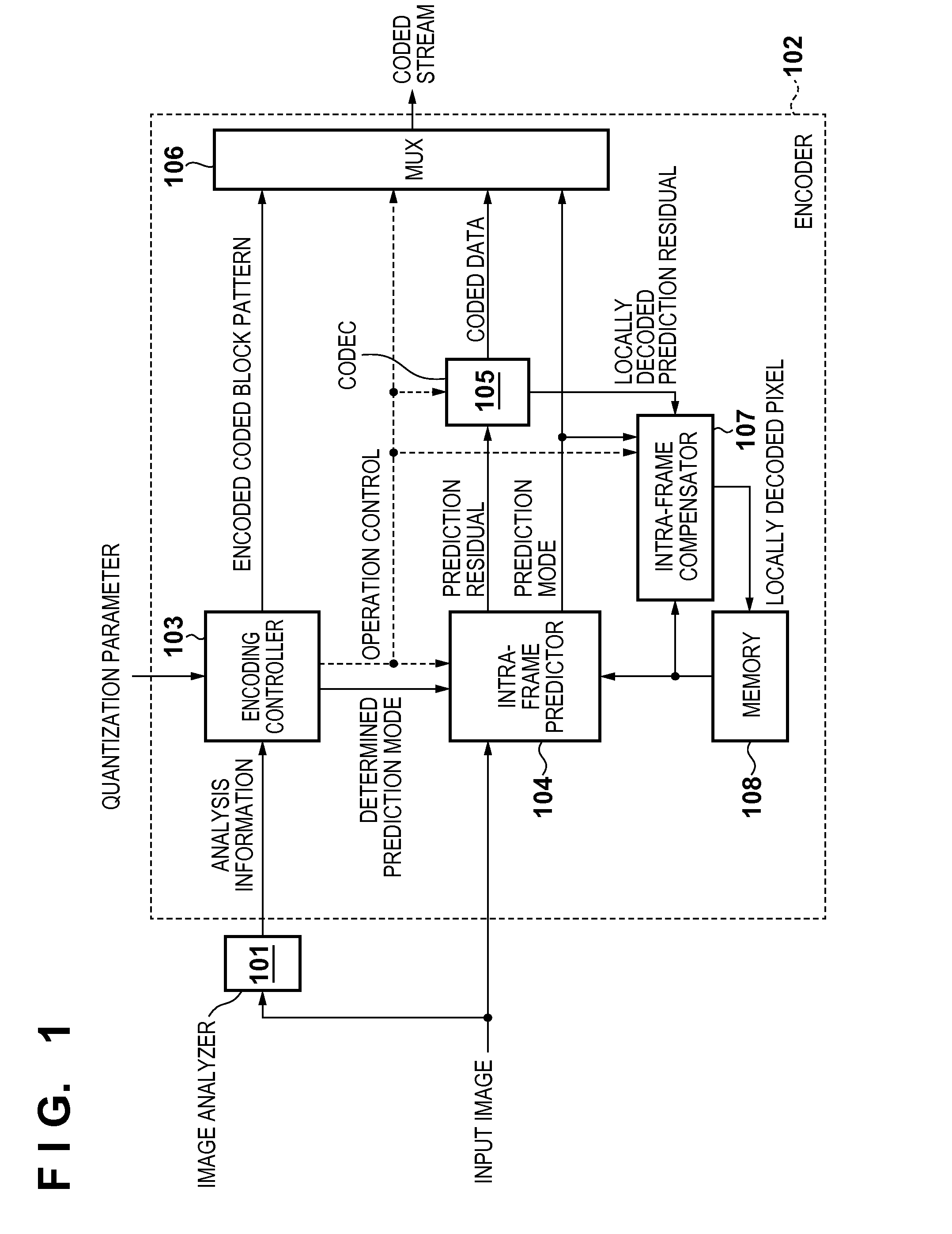
[0033]The arrangement of an image encoding apparatus according to the first embodiment will be described with reference to the block diagram of FIG. 1. The image encoding apparatus includes an image analyzer 101 and an encoder 102, as shown in FIG. 1.

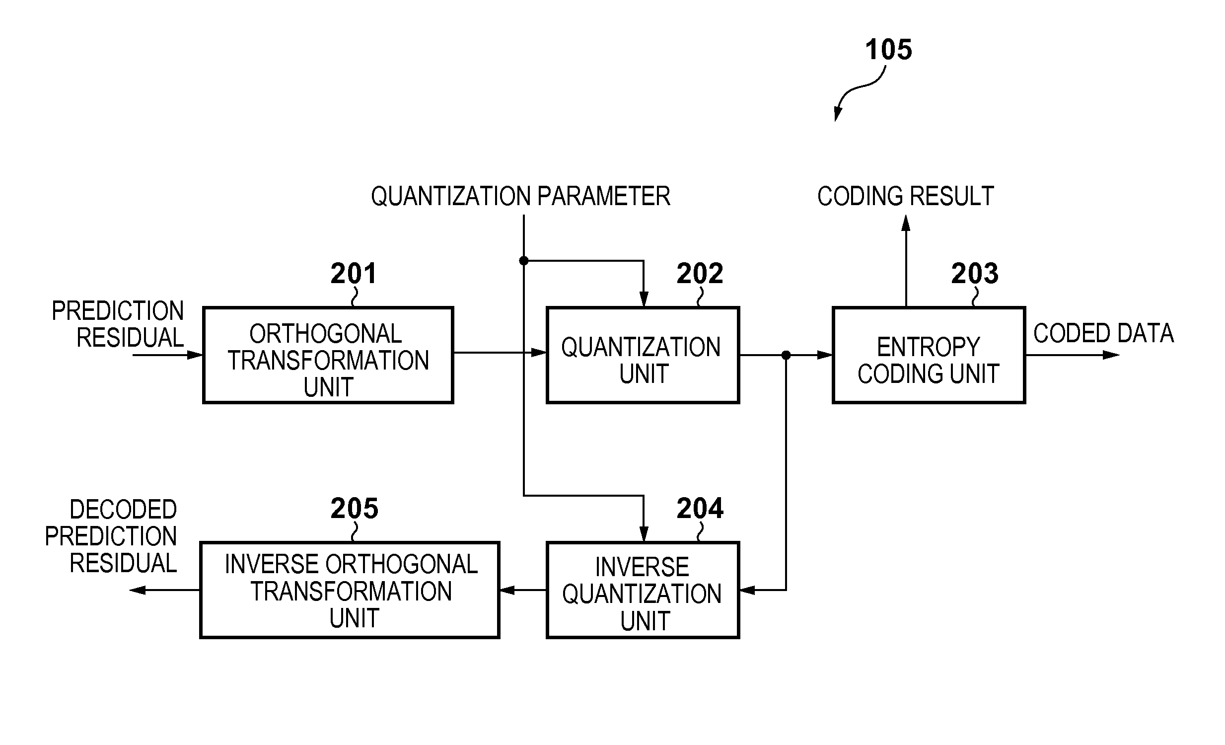
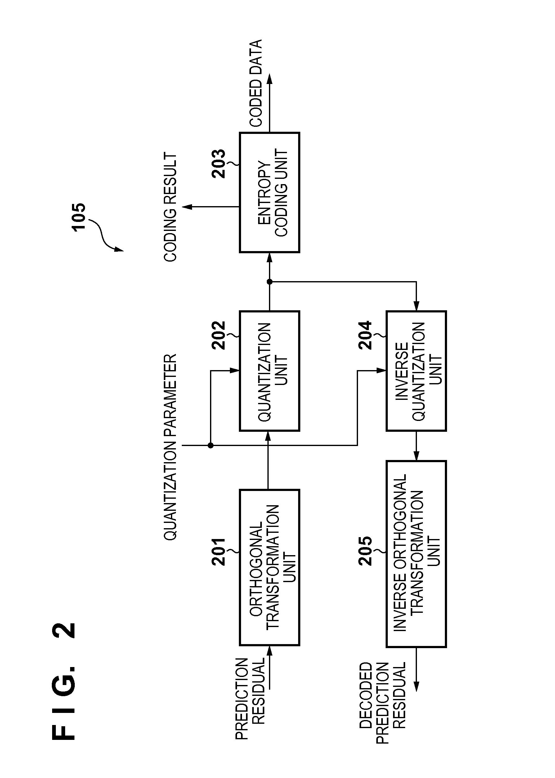
[0034]In the encoder 102, an encoding controller 103 receives a default quantization parameter for a coding target frame (frame image) from outside of the apparatus before the start of coding processing. The default quantization parameter is decided outside the apparatus based on a target code amount and a generated code amount that is the result of coding up to the immediately preceding frame. The encoding controller 103 performs adaptive quantization control to be described later using the default quantization parameter as a reference, and transfers a quantization parameter to be used in actual quantization to an encoder / decoder (CODEC) 105.

[0035]The encoding controller 103 also controls to, for example...

embodiment

Modification of Embodiment

[0111]The encoding controller 103 preferably has a clock control function of controlling a clock signal to internal processing of the encoder 102. During the period in which the processing of a sub block estimated as “Not Coded” is omitted, the clock signal supplied to the intra-frame predictor 104 and the CODEC 105 is stopped, thereby largely reducing power consumed by the clock signal as well.

[0112]To extract image characteristic information for adaptive quantization control, almost the same analysis information as that for estimation of the coding result can be used. Hence, the image characteristic information can be extracted by adding only small processing, and high image quality can be implemented by the adaptive quantization control without large overhead of processing (an increase in the power consumption).

[0113]The processing shown in FIGS. 10A to 11 can be implemented as a program to be executed by a microprocessor (CPU). When executing the progra...

second embodiment

[0125]An image encoding apparatus and an image encoding method according to the second embodiment of the present invention will be described below. Note that the same reference numerals as in the first embodiment denote the same parts in the second embodiment, and a detailed description thereof will be omitted.

[0126]In the first embodiment, an example has been described in which a coding result is estimated for each sub block including 4×4 pixels, and a coded block pattern obtained by integrating the coding results for each block is multiplexed on a coded stream as header information. However, in coding at a low bit rate, the header information including the coded block pattern also preferably has an information amount as small as possible. In HEVC, the transformation block size to define a coding result has a degree of freedom, and the size can adaptively be decided in coding. To reduce the code amount of header information, the size of the sub block is preferably made large. In th...


PUM


Abstract

An image analyzer divides an input image into first blocks in a coding unit and generates analysis information associated with intra-frame prediction of the input image for each first block. An intra-frame predictor divides the input image into second blocks in a predictive unit, and performs the intra-frame prediction to generate the prediction residual of each second block. A CODEC encodes a DC component or the prediction residual of the second block. An encoding controller estimates, for each first block, the coding result of the CODEC based on the analysis information and controls the intra-frame predictor and the CODEC based on the estimation.

Description

BACKGROUND OF THE INVENTION[0001]1. Field of the Invention[0002]The present invention relates to an image encoding apparatus and an image encoding method for coding a moving image.[0003]2. Description of the Related Art[0004]The development of digital technologies has popularized digital moving image capturing using a digital camera or a digital video camera. A digital moving image is generally compressed (coded) for efficient recording in a recording medium represented by a semiconductor memory. H.264 / MPEG-4 AVC (to be referred to as “H.264” hereinafter) is widely used as a moving image encoding method.[0005]International standardization activities for a more efficient encoding method succeeding to H.264 have recently started, and JCT-VC (Joint Collaborative Team on Video Coding) has been established between ISO / IEC and ITU-T. JCT-VC is promoting standardization of High Efficiency Video Coding (HEVC).[0006]To improve the coding efficiency, H.264 and HEVC employ intra-frame predicti...

Claims


Application Information

Patent Timeline
IPC IPC(8): H04N7/36
CPCH04N19/00696H04N19/52H04N19/176H04N19/149H04N19/593H04N19/11H04N19/107H04N19/12H04N19/124H04N19/14H04N19/137H04N19/18H04N19/194H04N19/80H04N19/59H04N19/91
Inventor HATTORI, HIDEAKI
Owner CANON KK
Why Eureka
Try Eureka