Radiative surface

a technology of radiative surface and surface, which is applied in the direction of recording information storage, transportation and packaging, instruments, etc., can solve the problems of inability to modulate, not being able to adapt to the changes of environment, and material entails applying high temperatures, so as to improve the flow of electrostatic charges, improve the effect of radiative surface, and improve the effect of heat control

Inactive Publication Date: 2014-04-17
THALES SA +1
View PDF4 Cites 3 Cited by
  • Summary
  • Abstract
  • Description
  • Claims
  • Application Information

AI Technical Summary

Benefits of technology

[0031]In the embodiment proposed by the invention, the electrodes are directly incorporated in a material, which makes it easier to implement the radiative surface comprising said material and allows for a better flow of the electr

Problems solved by technology

One drawback with this type of application is that they are not modulable and do not make it possible to adapt to changes of environment, a change of orientation of the satellite relative to the solar radiation for example.
Creating this type

Method used


Image

  • Radiative surface
  • Radiative surface
  • Radiative surface

Examples


Embodiment Construction

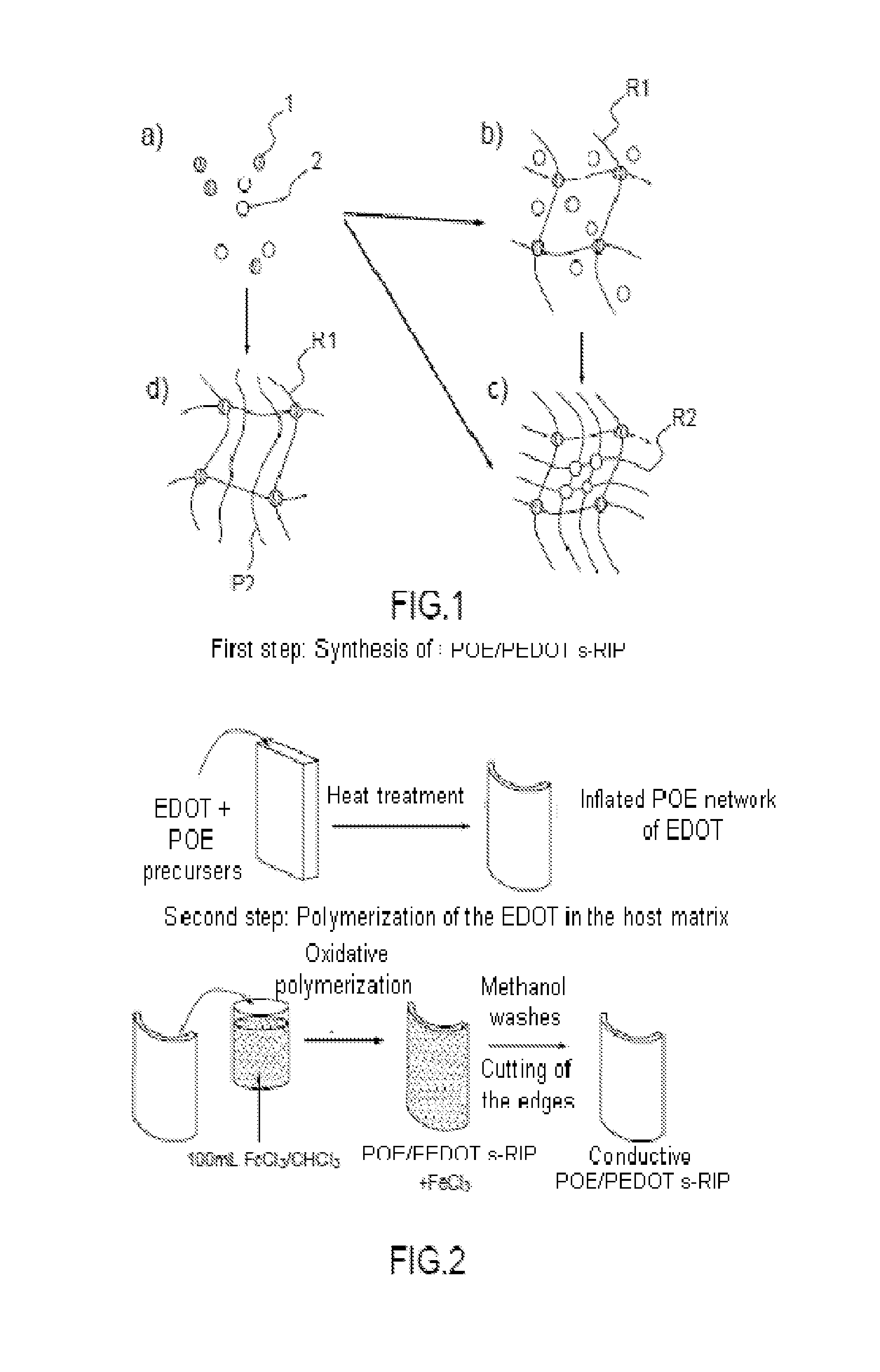
[0059]FIG. 1 represents the steps of formation of an interpenetrated network and of a semi-interpenetrated network. FIG. 1a represents a homogeneous mixture in solution of monomers comprising a monomer 1 and a monomer 2. FIG. 1b represents a first three-dimensional network R1 of a polymer comprising monomers 1, the three-dimensional polymer network R1 being inflated with a solution comprising the other monomers 2. FIG. 1c represents the first network R1 and a second polymer network R2 comprising the monomers 2. The first network R1 and the second network R2 are tangled together to form an interpenetrated network or RIP.

[0060]It is possible to produce an interpenetrated network sequentially in two steps: a first step of formation of a first network and a second step of formation of the second network. Alternatively, it is possible to produce an interpenetrated network in a single step of formation of the first and second network.

[0061]FIG. 1d represents a semi-interpenetrated network...


PUM

PropertyMeasurementUnit
Timeaaaaaaaaaa
Thicknessaaaaaaaaaa
Thicknessaaaaaaaaaa

Abstract

A radiative surface comprises a film comprising: a semi-interpenetrated or interpenetrated network of a first ion-conducting polymer and of a second electron- and electrochrome-conducting polymer; and an electrolyte for impregnating the network; the film comprising a first face intended to be in contact with the solar radiations, the first face being covered with a first metallic layer in order to reduce the absorptivity of the solar radiations. A method for creating the radiative surface is also provided.

Description

CROSS-REFERENCE TO RELATED APPLICATION[0001]This application claims priority to foreign French patent application No. FR 1202725, filed on Oct. 12, 2012, the disclosure of which is incorporated by reference in its entirety.FIELD OF THE INVENTION[0002]The invention relates to the active heat control of spacecraft and more particularly a radiative surface for spacecraft. Also, more specifically, the invention relates to a device with variable emissivity suitable for use as radiative surface for spacecraft.BACKGROUND[0003]The aim of heat control is essentially to guarantee that the temperature of the component parts of a spacecraft is maintained within a range of temperatures compatible with their specifications. It involves, notably, avoiding exceeding temperatures above which a material of the spacecraft would be damaged or destroyed, but also, remaining within a range of temperatures that makes it possible to guarantee a predetermined life span for an electronic component.[0004]Ther...

Claims


Application Information

Patent Timeline
IPC IPC(8): B64C1/38
CPCB64C1/38B64G1/226B64G1/50C23C14/20G02B5/208G02F1/157G02F1/15165Y10T428/265Y10T428/31533Y10T428/31699
Inventor DUDON, JEAN-PAULCHASTAING, EVELYNEVIDAL, FREDERICFABRE-FRANCKE, ISABELLEAUBERT, PIERRE-HENRICHEVROT, CLAUDETEISSIER, ANNE SANDRA
Owner THALES SA
Why Eureka
Try Eureka