Liquid ejecting apparatus

a liquid ejecting apparatus and liquid ejector technology, applied in printing and other directions, can solve the problems of insufficient wiping of mist, damage to the nozzle surface, and inability to adequately wipe down the mist, etc., and achieve the effect of limited pressure applied in the concave region

Inactive Publication Date: 2014-04-24
SEIKO EPSON CORP
View PDF5 Cites 6 Cited by
  • Summary
  • Abstract
  • Description
  • Claims
  • Application Information

AI Technical Summary

Benefits of technology

[0017]According to the configuration, when the wiping member is brought into contact with the nozzle surface, the pressure applied on the concave region may be limited. Thus, damage to the concave region of the nozzle surface, i.e., damage to the region having the nozzles formed thereon due to rubbing of the region with the wiping member may be suppressed. As a result, defective discharge may be inhibited.

Problems solved by technology

Deposition of mist on the nozzle surface can lead to defective ink discharge.
Therefore, when the mist of the UV ink becomes attached to the nozzle surface, an existing wiping mechanism is incapable of sufficiently wiping the mist.
In addition, increasing the force for wiping the mist increases a shear force applied between the nozzle surface and the mist, whereby the nozzle surface can be damaged (for example, a water repellent film applied on the nozzle surface is peeled off).
In particular, the shape of the UV ink droplets with high viscosity ejected from the nozzle stretches during flight and easily breaks up, thereby easily forming into a mist.
As a result, the number of times the nozzle surface is wiped increases, and as a result, the nozzle surface can be damaged more easily.
As a result, defective discharge may be inhibited.
According to the configuration, when the wiping member is brought into contact with the nozzle surface, the pressure applied on the concave region may be limited.
As a result, defective discharge may be inhibited.

Method used


Image

  • Liquid ejecting apparatus
  • Liquid ejecting apparatus
  • Liquid ejecting apparatus

Examples


Embodiment Construction

[0025]Embodiments of the invention will now be described with reference to the accompanying drawings. Moreover, although preferred concrete examples of the invention are described in the following embodiments, the scope of the invention is not intended to be limited to the aspects unless otherwise specified as limiting the invention in the following description. In addition, the following description includes an ink jet printer (hereinafter referred to as a printer) having an ink jet recording head, i.e., a kind of liquid ejecting head (hereinafter referred to as a recording head) as a liquid ejecting apparatus of an aspect of the invention.

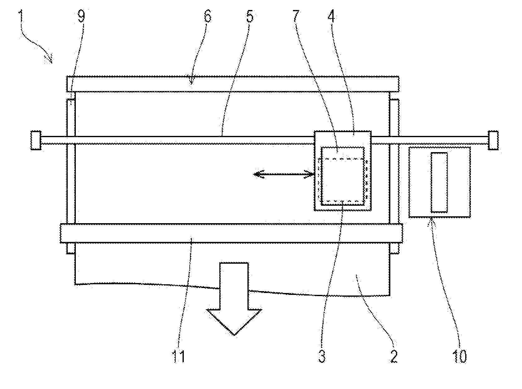
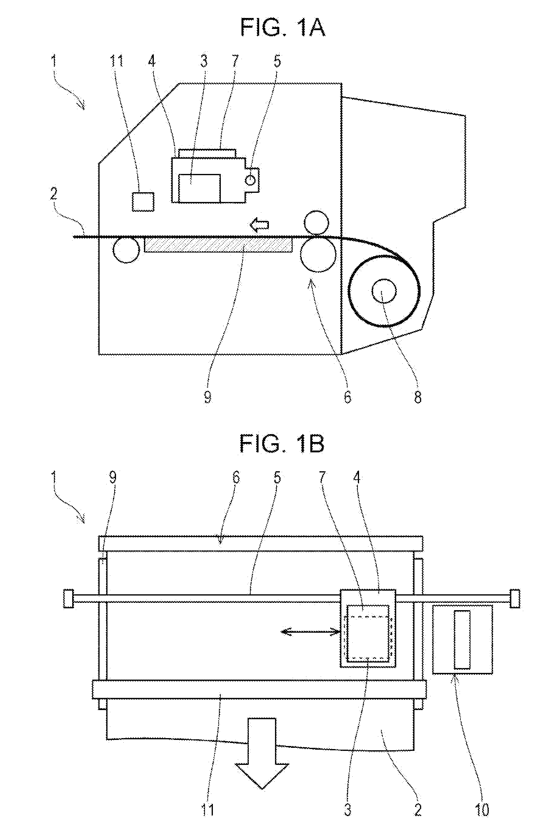
[0026]A configuration of a printer 1 will be described with reference to FIGS. 1A and 1B. The printer 1 is an apparatus for recording an image or the like by ejecting a liquid ink to the surface of a recording media 2 (a kind of deposition target) such as a recording paper. The printer 1 includes a recording head 3, a carriage 4 for carrying the ...


PUM


Abstract

A liquid ejecting apparatus includes a liquid ejecting head which is capable of ejecting a photo-curable liquid to be cured by irradiation with light from nozzles which open at a nozzle surface of a nozzle-forming member; a wiping unit for wiping the nozzle surface with a wiping member in contact with the nozzle surface, a portion of the wiping member in contact with the nozzle surface being made of cloth; and a heating mechanism for generating heat to heat the nozzle surface; wherein the wiping member is capable of wiping the nozzle surface in a state in which an ink splash of a photo-curable liquid attached on the nozzle surface has been softened by heating of the heating mechanism.

Description

BACKGROUND[0001]1. Technical Field[0002]The present invention relates to a liquid ejecting apparatus including a liquid ejecting head for ejecting a liquid from nozzles which open at a nozzle surface, and more particularly, relates to a liquid ejecting apparatus including a wiping unit for wiping a nozzle surface.[0003]2. Related Art[0004]A liquid ejecting apparatus is an apparatus including a liquid ejecting head from which various liquids are ejected. The liquid ejecting apparatus may be, for example, an image recording apparatus such as an ink jet printer and an ink jet plotter, and recently, it has been applied to various manufacturing systems by taking advantage of the ability to accurately eject a very small amount of liquid to a desired position on various media. For example, it has been applied to a display manufacturing system for manufacturing a color filter of a liquid crystal display or the like, an electrode forming system for forming electrodes of an organic electrolum...

Claims


Application Information

Patent Timeline
Patent Type & Authority Applications(United States)
IPC IPC(8): B41J2/165
CPCB41J2/16535B41J2/16552
Inventor OZAWA, KINYA
Owner SEIKO EPSON CORP
Why Eureka
Try Eureka