Fuel cell, separator plate for a fuel cell, and method of operation of a fuel cell

a technology of separator plate and fuel cell, which is applied in the field of fuel cells to achieve the effect of high reliability and free from cell performance degradation

Inactive Publication Date: 2009-01-20
PANASONIC CORP
View PDF36 Cites 7 Cited by
  • Summary
  • Abstract
  • Description
  • Claims
  • Application Information

AI Technical Summary

Benefits of technology

[0017]In view of the above problems, an object of the present invention is to provide a highly reliable polymer electrolyte fuel cell that is significantly free from cell performance degradation or instability that tends to be caused by clogging of gas flow channels with condensed water and generated water during a low load operation.
[0018]In order to solve the above problems, the present invention provides a highly reliable polymer electrolyte fuel cell capable of securing sufficient gas velocity by forming a plurality of independent gas flow channels in one face of a separator plate and limiting the gas supply region in a low load operation.
[0026]Because the present invention can reduce clogging of the gas flow channel with water in a low load operation, it is possible to prevent cell performance degradation or instability in the low load operation.

Problems solved by technology

As a result, the cell performance becomes both unstable and degraded due to water clogging or the like.
First, the aforementioned flooding occurs. A common approach to avoiding flooding is to increase the pressure loss of the supplied gases to blow the condensed water off. However, the increase in the pressure loss of the supplied gases causes an extreme increase in the power of auxiliaries of the system, such as a gas blower or a compressor, thereby inviting a decrease in system efficiency.
Second, the wettability (contact angle) of the gas diffusion layer and the carbon carrying the catalyst layer by water changes with time, so that the discharging efficiency of the condensed water lowers with time, affecting cell durability.
Third, the wettability (contact angle) of the gas diffusion layer and the carbon carrying the catalyst layer changes with time, resulting in a time variance in the ratio of the flow rate of the gas flowing through the gas diffusion layer to the flow rate of the gas flowing through the gas flow channel of the separator plate. Specifically, the wettability of the gas diffusion layer increases with time, leading to an increase in the amount of stagnant condensed water in the gas diffusion layer. Accordingly, the supply of gas to the electrode is locally hindered, which causes a decrease in current density in the area where the gas supply is hindered. Therefore, the difference in the current density increases within a unit cell, consequently lowering the characteristics of the whole fuel cell.
Fourth, the time-varying change in the ratio of the gas flow rate of the gas flowing through the gas diffusion layer to the flow rate of the gas flowing through the gas flow channel of the separator plate changes the proportion of “underflow.” The term “underflow” as used herein refers to the flow of gas passing through the gas diffusion layer between adjacent flow channels of the separator plate. If there were no gas diffusion layer, all of the supplied gas would flow along the gas flow channel. In fact, however, because of the existence of the gas diffusion layer adjacent to the gas flow channel, some of the supplied gas flows through the gas diffusion layer between adjacent flow channels, particularly in the case of a serpentine-type gas flow channel. For example, in a continuous serpentine-type gas flow channel, consisting of linear parts and turn parts, the direction of gas flowing through one linear part is opposite to the direction of gas flowing through the adjacent linear part. Thus, the underflow of gas passing through the gas diffusion layer occurs in such a manner as to balance the pressure loss of gas flowing from upstream to downstream through the one linear part and the pressure loss of gas flowing through the gas diffusion layer under the rib between the adjacent linear parts from upstream to downstream.
However, the increase in the wettability of the gas diffusion layer with time and the corresponding increase in the amount of stagnant condensed water in the gas diffusion layer cause a phenomenon that the underflow of gas flowing through the gas diffusion layer is hindered.
Thus, in the case of the serpentine-type flow channel, the amount of underflow through the gas diffusion layer decreases with time near the turn parts of the gas flow channel, thereby resulting in a decrease in the current density in the area of the gas diffusion layer where the gas supply is hindered.
Therefore, the difference in current density increases within a unit cell, consequently lowering the characteristics of the whole fuel cell.
Further, if the flooding phenomenon occurs on the anode side, the fuel gas becomes depleted, a condition that is fatal to the cell.
As a result, the anode catalyst layer is destroyed due to the loss of carbon from the catalyst layer.
Specifically, if the load is reduced to half that of the rated operation, for example, the flow rates of the fuel gas and the oxidant gas must also be reduced to about half those of the rated operation; otherwise, extra fuel and oxidant gases will be used, resulting in a decrease in power generating efficiency.
However, if the low load operation is performed with the gas utilization rates constant, the velocity of the gas flowing through the gas flow channel decreases, so that the condensed water and generated water are not discharged to the outside of the separator plate.
Therefore, the above-described flooding phenomenon occurs, and the cell performance becomes degraded or unstable.

Method used


Image

  • Fuel cell, separator plate for a fuel cell, and method of operation of a fuel cell
  • Fuel cell, separator plate for a fuel cell, and method of operation of a fuel cell
  • Fuel cell, separator plate for a fuel cell, and method of operation of a fuel cell

Examples


embodiment 1

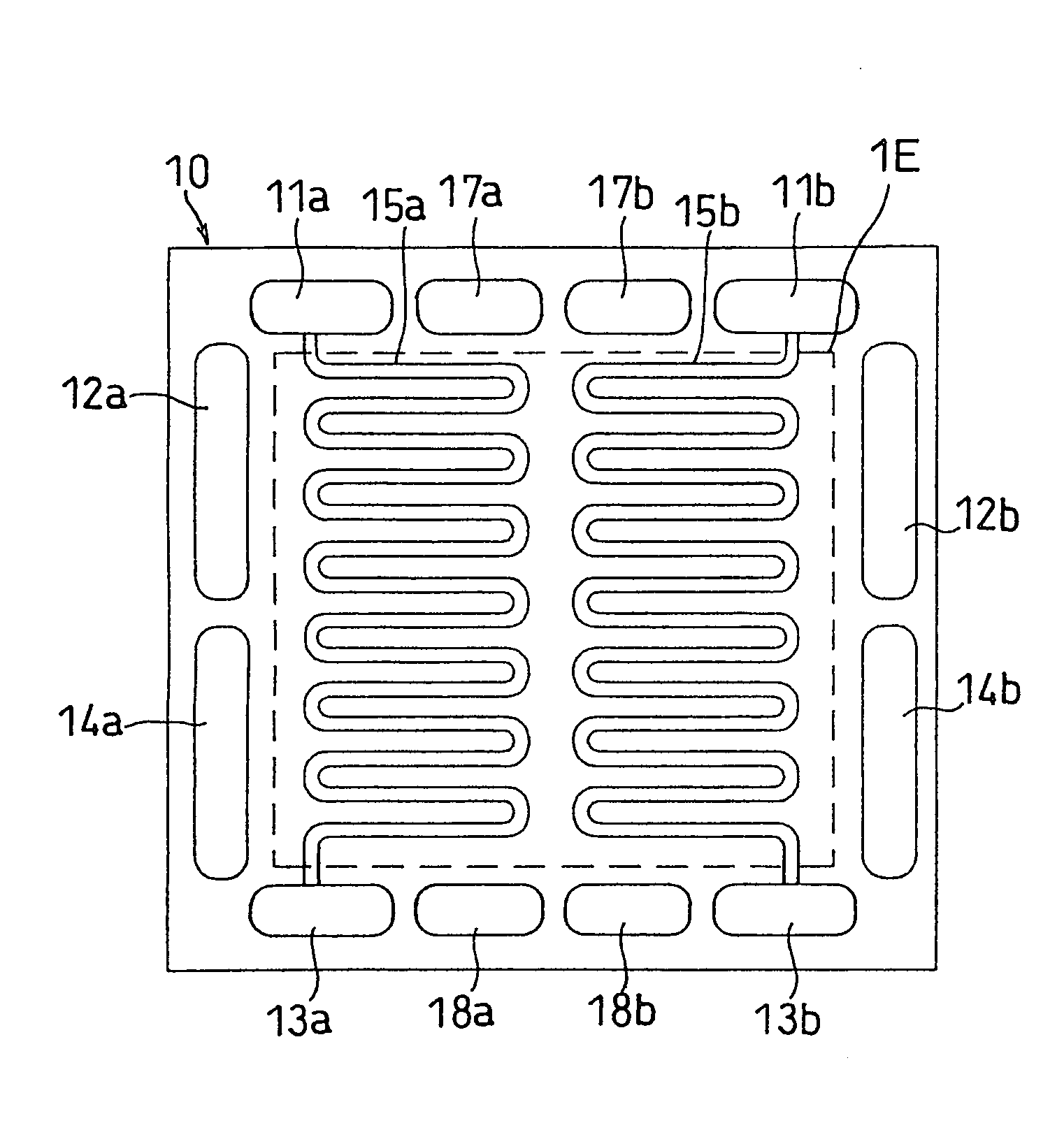
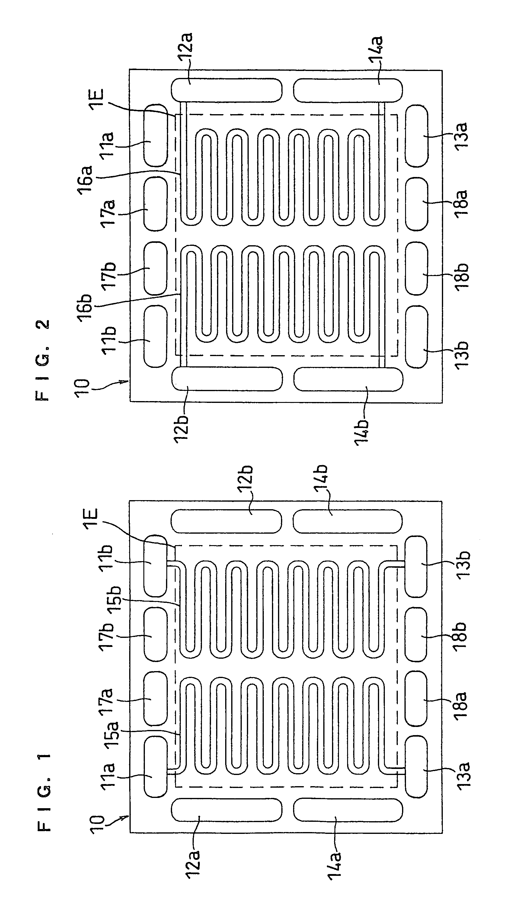
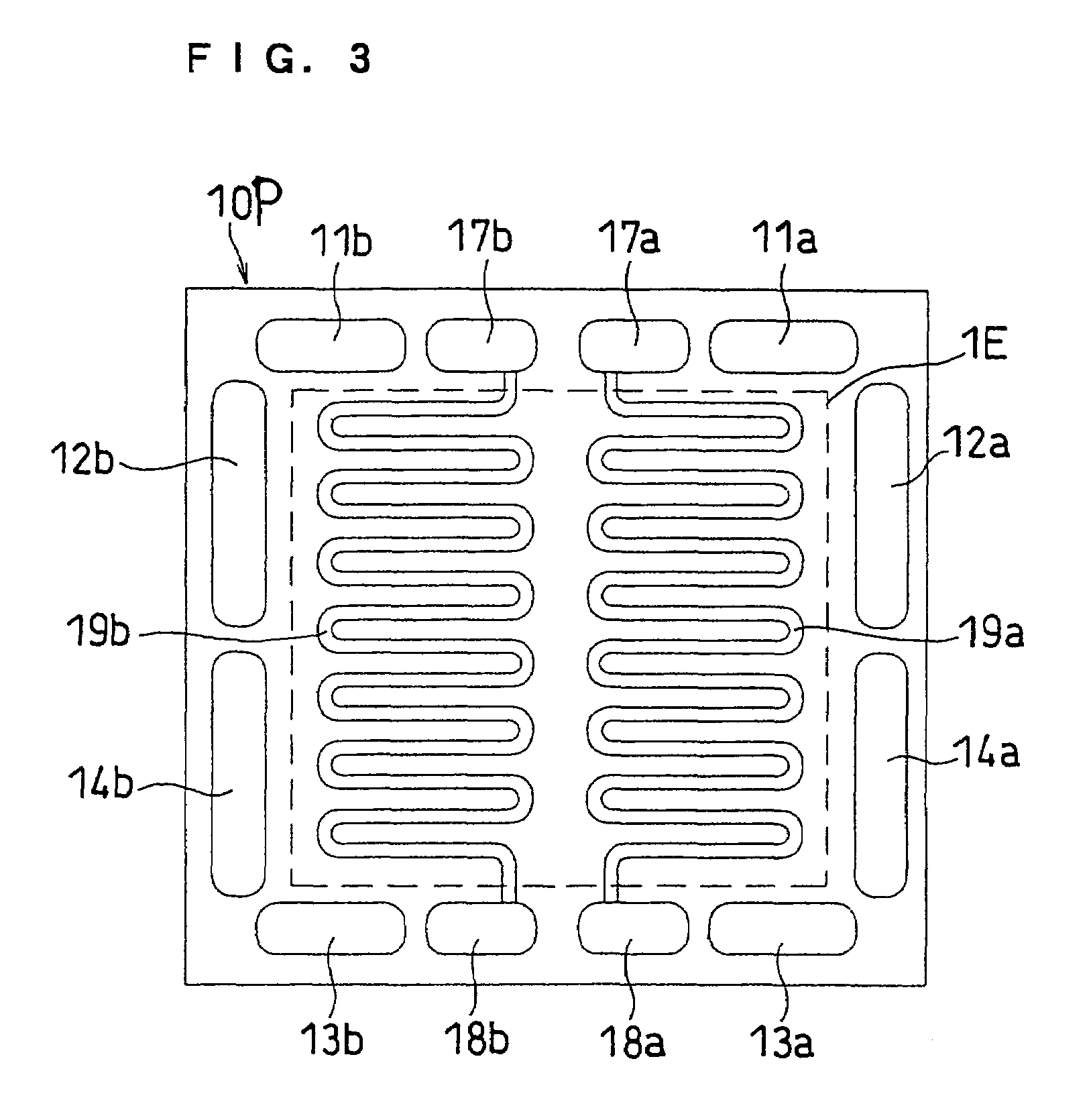
[0070]FIGS. 1, 2 and 3 illustrate separator plates of this embodiment. FIG. 1 is a front view of the anode facing side of a separator plate 10, and FIG. 2 is a back view thereof as well as a front view of the cathode facing side. FIG. 3 is a front view of a cathode facing side of an anode side separator plate 10P including a cooling section.

[0071]A separator plate 10 has fuel gas inlet-side manifold apertures 11a and 11b, fuel gas outlet-side manifold apertures 13a and 13b, oxidant gas inlet-side manifold apertures 12a and 12b, oxidant gas outlet-side manifold apertures 14a and 14b, cooling water inlet-side manifold apertures 17a and 17b, and cooling water outlet-side manifold apertures 18a and 18b. The separator plate 10 has, on the anode facing side, independent fuel gas flow channels 15a and 15b communicating with the inlet-side manifold apertures 11a and 11b and the outlet-side manifold apertures 13a and 13b, respectively. On the cathode facing side, the separator plate 10 has i...

embodiment 2

[0079]This embodiment describes an example of dividing each of the fuel gas flow channel and the oxidant gas flow channel into two parts, such that the area ratio of the flow channel regions of the two divided gas flow channels is 2:1. The flow channel regions in which the independent gas flow channels are located may be different or the same in area (size), as necessary. The term “flow channel region” as used herein refers to the region of a separator plate at which each flow channel is located. The area ratio is based on the areas of the flow channels projected onto the plane of the separator plate. The cross-sections of the different flow channels may be the same or different. If the cross-sections are the same, an area ratio of 2:1 indicates that there is also a length ratio of about 2:1. In any event, the flow channels may have the same or different total volumes, and the same or different total volumes may be provided by varying the cross-section or length of the channels.

[008...

embodiment 3

[0082]FIGS. 7 and 8 illustrate a separator plate of this embodiment. This is an example of dividing the electrodes of an MEA into two physically separate sections, in correspondence with the two divided gas flow channels. The physical separation between the two electrode sections prevents or diminishes migration of water and reaction gases from one electrode section to the other. The physical separation can be provided by an air gap between the electrode sections or by interposing a water-impermeable material and a reaction gas-impermeable material therebetween. An electrode section 1Ea of the MEA is provided in agreement with the fuel gas flow channel 15a and the oxidant gas flow channel 16a, while an electrode section 1Eb is provided in agreement with the fuel gas flow channel 15b and the oxidant gas flow channel 16b. Except for these electrode sections 1Ea and 1Eb, this embodiment has the same constitution as that of Embodiment 1.


PUM

PropertyMeasurementUnit
particle sizeaaaaaaaaaa
thickaaaaaaaaaa
thickaaaaaaaaaa

Abstract

A fuel cell includes a stack of unit cells, each including: a hydrogen-ion conductive polymer electrolyte membrane; an anode and a cathode sandwiching the polymer electrolyte membrane; an anode-side conductive separator plate having a gas flow path for supplying and discharging a fuel gas to and from the anode; and a cathode-side conductive separator plate having a gas flow path for supplying and discharging an oxidant gas to and from the cathode. At least one of the anode-side and cathode-side separator plates has, in one face thereof, a plurality of independent gas flow channels, which constitute the gas flow path. When the fuel cell is operated at low load, the fuel gas or the oxidant gas is supplied to one or more of the plurality of independent gas flow channels, so that the fuel cell is capable of securing sufficient gas velocity.

Description

FIELD OF THE INVENTION[0001]The present invention relates to fuel cells for use in portable power sources, electric vehicle power sources, domestic cogeneration systems or the like, and, more particularly, to fuel cells including a polymer electrolyte membrane and an operation method thereof.RELATED ART OF THE INVENTION[0002]A fuel cell including a polymer electrolyte membrane generates electric power and heat simultaneously by electrochemically reacting a fuel gas containing hydrogen with an oxidant gas containing oxygen, such as air. The fuel cell essentially comprises a polymer electrolyte membrane that selectively transports hydrogen ions and a pair of electrodes (anode and cathode) formed on both sides of the polymer electrolyte membrane. The electrode is composed of a catalyst layer formed on each side of the polymer electrolyte membrane and a gas diffusion layer formed on the outer face of the catalyst layer. The catalyst layer is composed mainly of a carbon powder carrying a...

Claims


Application Information

Patent Timeline
Patent Type & Authority Patents(United States)
IPC IPC(8): H01M8/04H01M4/94H01M8/00H01M8/02H01M8/10H01M8/24
CPCH01M8/0258H01M8/0267H01M8/04179H01M8/04298H01M8/04746H01M8/0263H01M2008/1095Y02E60/50H01M8/241H01M8/2457H01M8/2483H01M8/2484
Inventor TAKEGUCHI, SHINSUKEHATOH, KAZUHITOOHARA, HIDEOGYOTEN, HISAAKI
Owner PANASONIC CORP
Why Eureka
Try Eureka