
3D scanning system and method of obtaining 3D image

a scanning system and 3d technology, applied in the field of 3d laser scanning system, can solve the problems of increasing the volume of a whole sensor, the cost of a unit sensor, and the low vertical resolution of the unit, and achieves excellent vertical resolution, high scanning speed, and small volume

Active Publication Date: 2014-04-24
KOREA INST OF IND TECH
View PDF6 Cites 112 Cited by
  • Summary
  • Abstract
  • Description
  • Claims
  • Application Information

AI Technical Summary

Benefits of technology

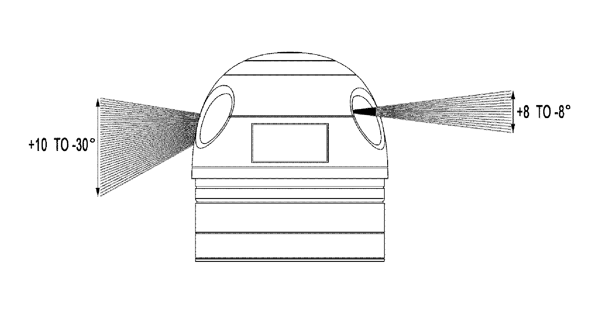
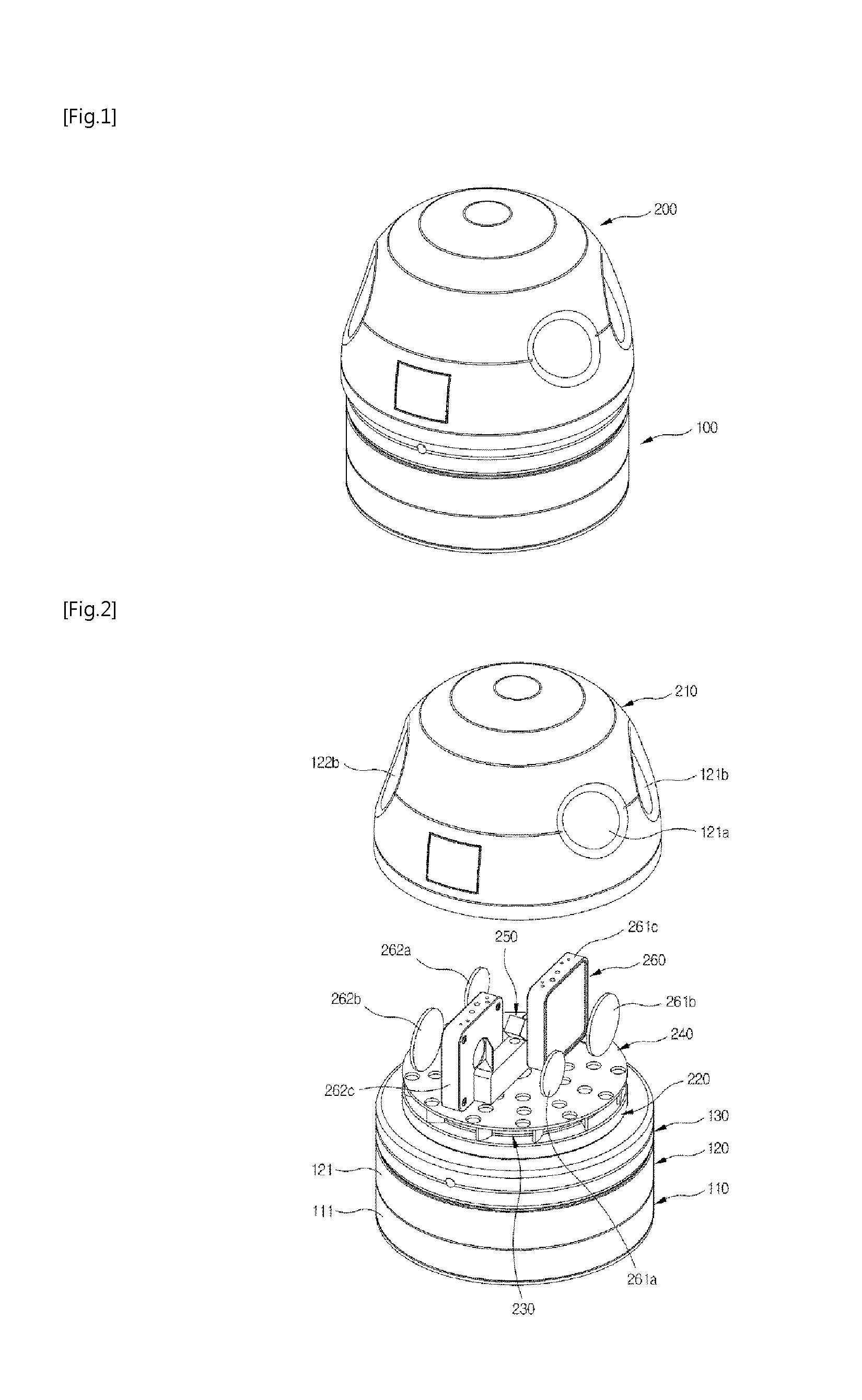
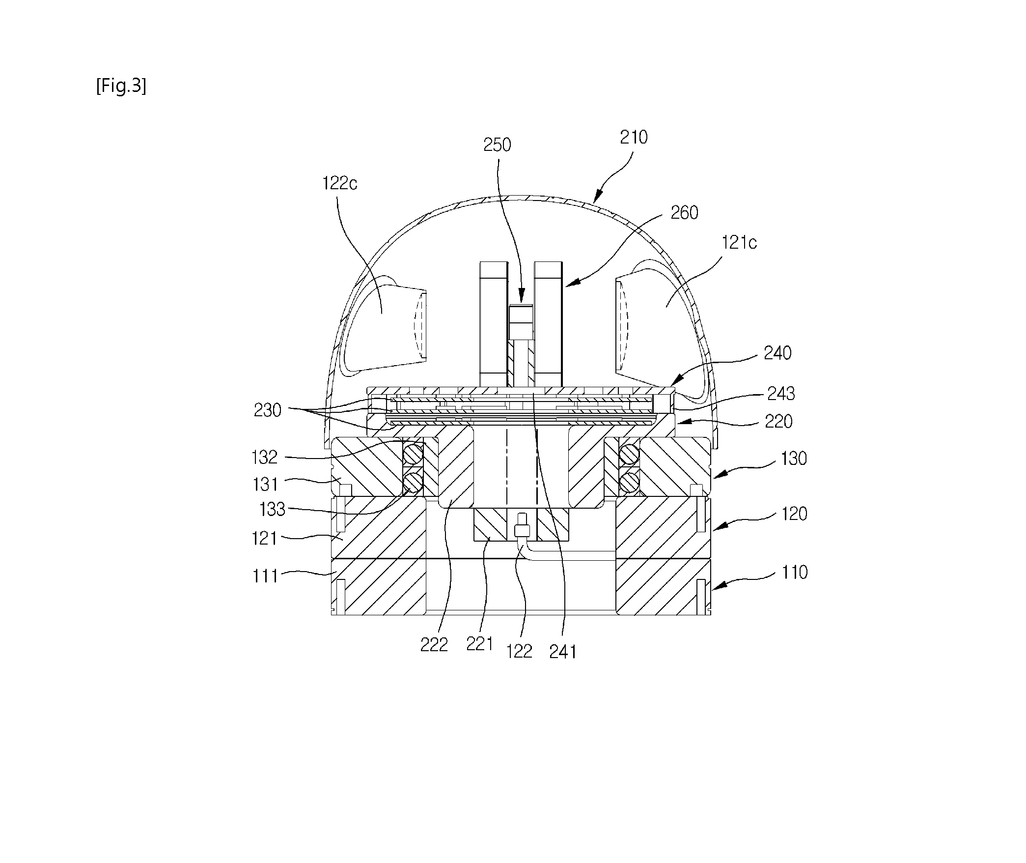
The present invention is related to a 3D laser scanning system and its method. The system has a high scanning speed and small volume compared to traditional systems. It uses a narrow-angle line laser for long distance sensing and a wide-angle line laser for short distance sensing, allowing for a wide field of view and dense point cloud data. The system also separates the laser source and its cooling unit from the light transmitting and receiving module, making it lighter and more compact. Overall, the invention provides a faster, smaller, and more efficient 3D scanning system.

Problems solved by technology

In case of the first assembly, in order to obtain point cloud data on a long distance, it is needed to increase the laser output power, accordingly which leads to drawbacks in that the volume of a whole sensor increases and the cost of a unit sensor rises.
Moreover, since the space between point cloud data becomes larger as a distance becomes long, the LIDAR system has a drawback in that a point cloud data obtained from a long distance object has low vertical resolution and thus the reliability of its processed data also decreases.
Most of all, since 32 or 64 laser diodes are individually installed, emission angles are different and thus it is difficult to precisely calibrate a laser diode and a corresponding photo detector individually.
Moreover, since a general 3D laser scanning system has a structure in which both a laser source and a light transmitting / receiving unit are installed and rotated in a rotation-driving device, a rotary motor having great capacity is needed due to the weight of a laser source and a cooling structure for cooling the laser source and thus there are drawbacks in that the manufacturing cost of a scanning system increases and its volume increases as well.

Method used


Image

  • 3D scanning system and method of obtaining 3D image
  • 3D scanning system and method of obtaining 3D image
  • 3D scanning system and method of obtaining 3D image

Examples


Embodiment Construction

[0052]Exemplary embodiments will be described below in detail on the basis of exemplary embodiments of the present invention with reference to the accompanying drawings.

[0053]Moreover, the terms or words used in the specification and claims should not be construed as typical and denotative meanings but be construed as meanings and concepts that match the technical spirit of the present invention on the basis of a principle that inventors may properly define the concepts of the terms in order to describe their invention in a best way. Thus, since the embodiments described in the specification and the configurations shown in the drawings are just exemplary embodiments of the present invention and do not thoroughly represent the technical spirit of the present invention, there may be, when filing this application, various equivalents and variations that may replace the embodiments and the scope of the present invention are not limited to the following embodiments.

[0054]A 3D laser scann...


PUM


Abstract

Disclosed are a 3D laser scanning system and a method of obtaining a 3D image by using the system that detect, with a linear array type photo detector, a reflected light reflected from a target after rotation-emitting a line-shaped pulsed laser light through 360 degrees and obtain a 3D image through point cloud data obtained by measuring a distance to the target.

Description

TECHNICAL FIELD[0001]The present invention relates to a 3D laser scanning system and a method of obtaining a 3D image that detect, with a linear array type photo detector, a reflected light from a target after emitting a line-shaped pulsed laser light through 360 degrees and generating a 3D image through point cloud data obtained by calculating a distance to the target.[0002]More particularly, the present invention relates to a 3D laser scanning system and a method of obtaining a 3D image by using the system that may obtain wide-angle data in a short distance and long distance data having an excellent vertical resolution without raising an optical output in a long distance by configuring the line-shaped pulsed laser light and the linear array photo detector at different field of views and a symmetric alignment.BACKGROUND ART[0003]A 3D image sensor called light detection and ranging (LIDAR) or laser detection and ranging (LADAR) is a system that may catch the reflected light energy f...

Claims


Application Information

Patent Timeline
IPC IPC(8): G01B11/25G01S17/87G01S17/89
CPCG01B11/25G01S7/4813G01S7/4814G01S17/42G01S17/87G01S17/89G01S7/4817
Inventor BAEG, SEUNG-HOPARK, SANG-DEOKSHIN, JIN-OKCHO, KUK
Owner KOREA INST OF IND TECH
Learn More