Computed radiography positioning method and system

a radiography and positioning method technology, applied in the field of computed radiography, can solve the problems of inconvenient use of radiation sources, cumbersome and uncomfortable patients, and difficult alignment of dental or intraoral radiography holders, so as to improve the ability to align radiation sources and advance the art of intraoral radiography.

Inactive Publication Date: 2014-04-24
CARESTREAM DENTAL TECH TOPCO LTD
View PDF4 Cites 8 Cited by
  • Summary
  • Abstract
  • Description
  • Claims
  • Application Information

AI Technical Summary

Benefits of technology

[0014]An object of the present invention is to advance the art of intraoral radiography by providing apparatus and methods that improve the ability to align the radiation source and image detector.

Problems solved by technology

Alignment is difficult for dental or intraoral radiography.
Holders of this type can be cumbersome and uncomfortable to the patient.
Holders and other positioning devices are not error-proof, and positioning errors with these devices can mean that the images obtained are not suitable for use in detecting some types of problems.
Poorly aligned detectors can be the cause of problems such as cone cuts, missed apices, and elongation and related angulation or parallax errors, for example.
These alignment problems can require re-takes, additional image captures to acquire an acceptable image.
Re-takes are undesirable due to the additional x-ray radiation exposure to the patient and because of prolonged patient discomfort with the detector held in the mouth for a longer time period.
These work where the radiation detector can be seen, but fall short of what is needed where the detector is not visible, such as with intraoral imaging.
This can complicate the alignment task, since it can be difficult to obtain the desired oblique angle for a detector 20 that is not visible when the patient's mouth is closed.
At least one drawback of alignment methods relates to lack of guidance for correcting for mis-alignment.
Some methods for reporting the alignment information, such as providing information on an operator console, for example, can be difficult to use when making position adjustments.

Method used


Image

  • Computed radiography positioning method and system
  • Computed radiography positioning method and system
  • Computed radiography positioning method and system

Examples


Embodiment Construction

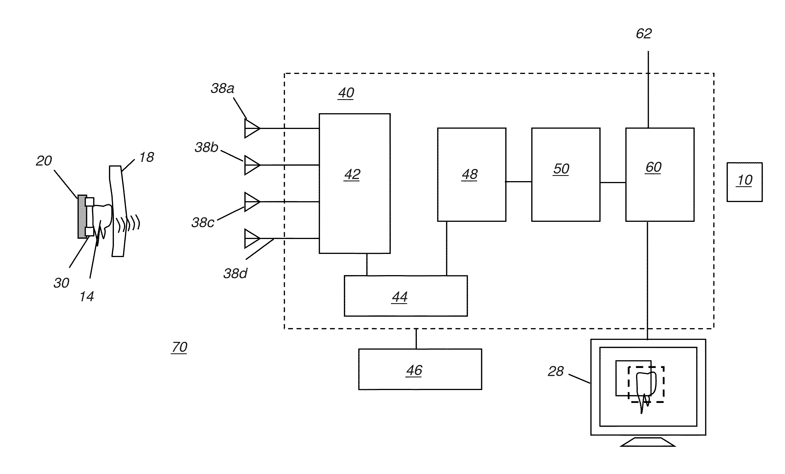
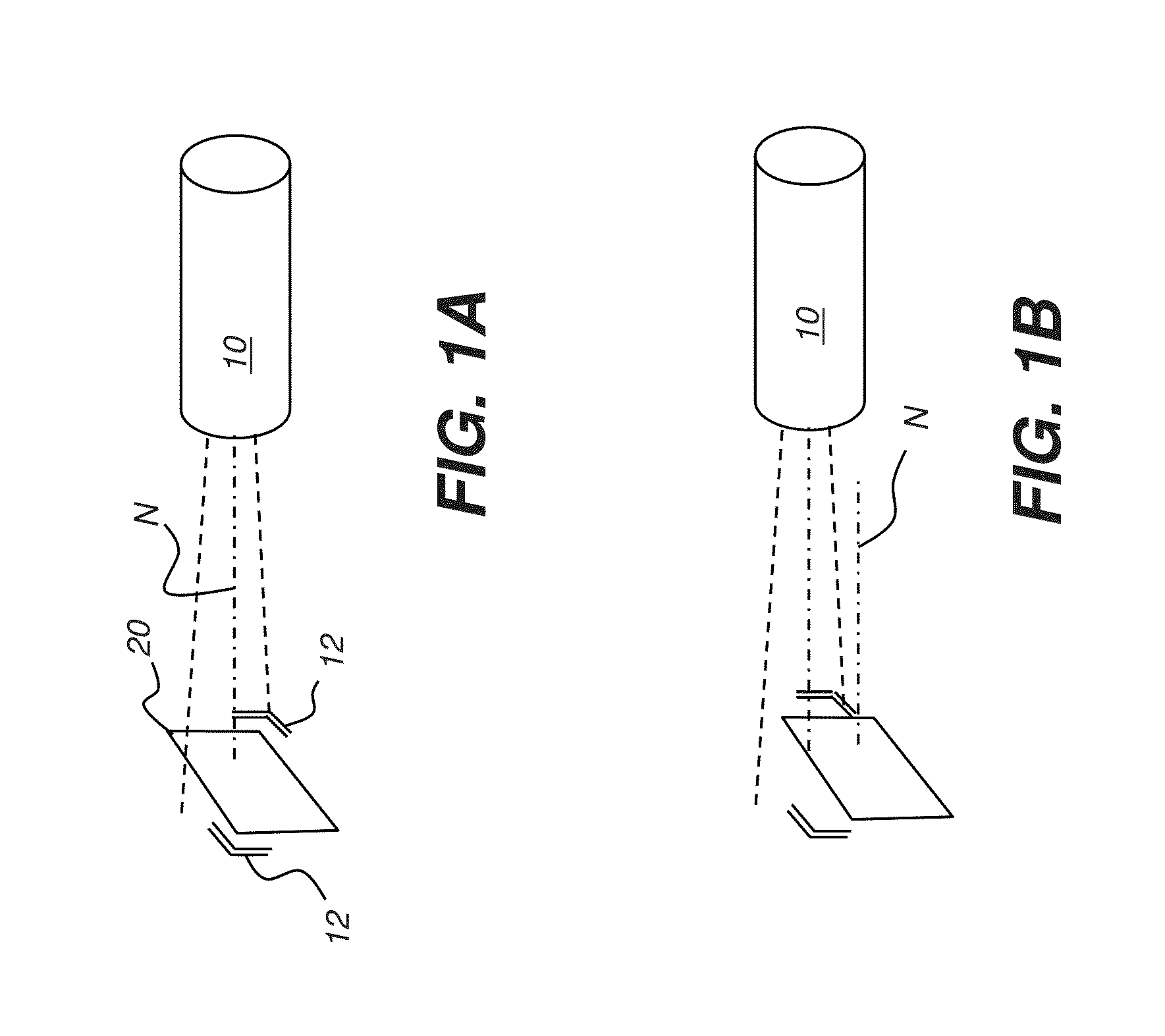
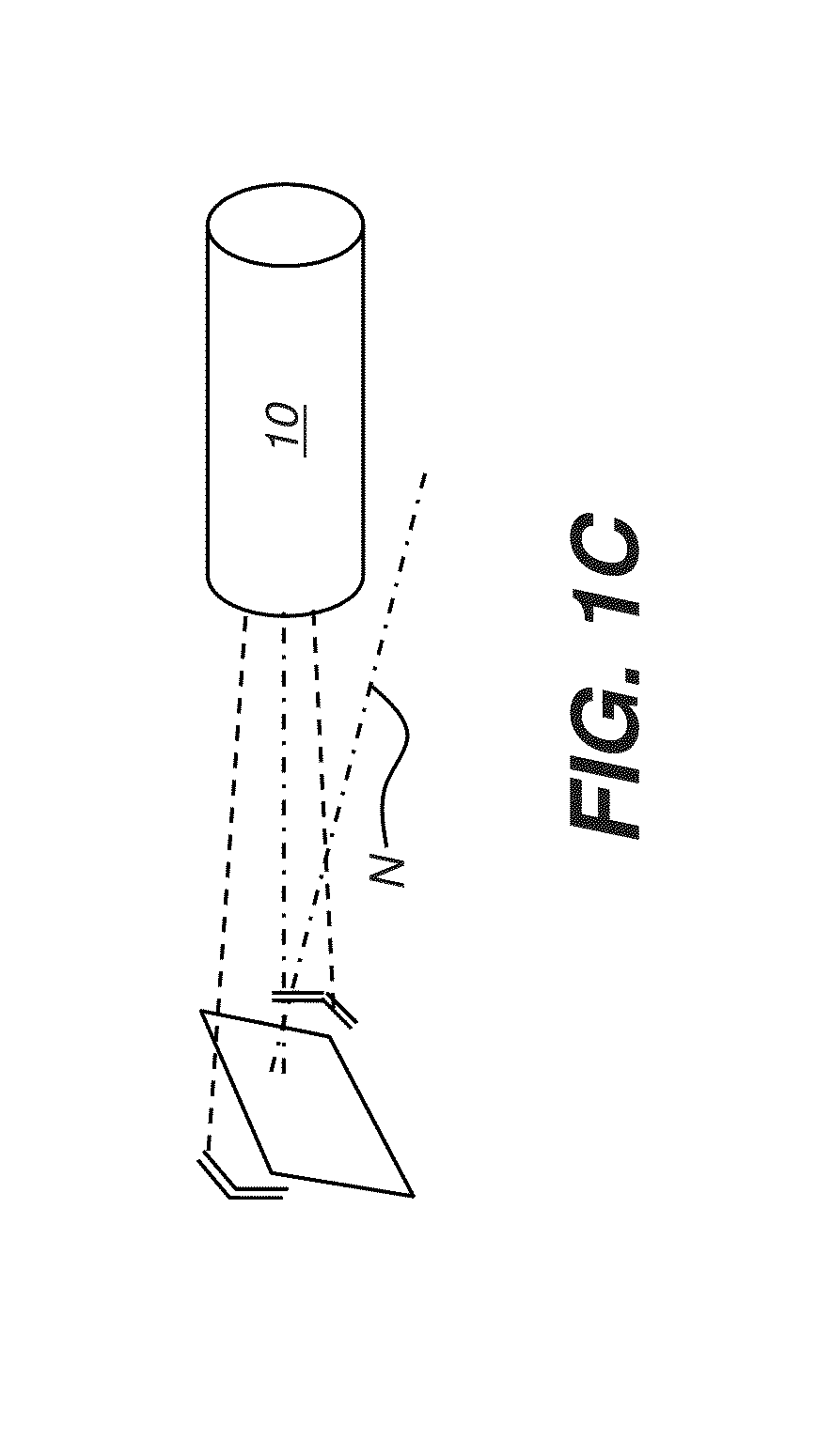
[0037]The following is a detailed description of the preferred embodiments of the invention, reference being made to the drawings in which the same reference numerals identify the same elements of structure in each of the several figures.

[0038]Figures shown and described herein are provided in order to illustrate key principles of operation according to the present invention. Some exaggeration of relative dimensions and scale may be necessary in order to emphasize basic positional and structural relationships or principles of operation.

[0039]Where they are used, the terms “first”, “second”, and so on, do not necessarily denote any ordinal or priority relation, but may be used for more clearly distinguishing one element or time interval from another. In the context of the present disclosure, the terms “operator”, “technician”, “user”, and “practitioner” are considered to be equivalent.

[0040]In the context of the present disclosure, the equivalent terms “image detector”, “imaging dete...


PUM


Abstract

An apparatus for obtaining an intraoral x-ray image from a patient, the apparatus has an x-ray source and a radio-frequency transceiver coupled to the x-ray source and energizable to transmit an interrogation signal, wherein the transceiver is in signal communication with four or more antennae. An intraoral image detector forms an image upon exposure to radiation received from the x-ray source. A radio-frequency transponder is coupled to the image detector and is configured to respond to the interrogation signal by transmitting a wireless response signal. A control logic processor is in communication with the transceiver and provides an output signal indicative of the spatial position of the image detector according to response signals received from the transponder at the four or more antennae. An indicator responds to the output signal by indicating the relative position of the image detector.

Description

CROSS REFERENCE TO RELATED APPLICATIONS[0001]The present application claims priority to U.S. Provisional Patent Application No. 61 / 715,862 filed on Oct. 19, 2012 entitled COMPUTED RADIOGRAPHY POSITIONING METHOD AND SYSTEM, to Berger et al., and incorporated herein by reference in its entirety.FIELD OF THE INVENTION[0002]The present invention relates generally to computed radiography, including medical and dental applications.BACKGROUND[0003]The use of an information carrier plate (also referred to as a phosphor plate or phosphor storage plate) as a detector for obtaining visually perceptible contrast upon exposure to X-rays is known in the art as computed radiography (CR) and is described for example in U.S. Pat. No. 7,211,785 entitled “SCANNING APPARATUS” to Berger et al., incorporated herein by reference. In Computed Radiography (CR), a phosphor carrier plate is exposed to x-ray or other short-wavelength ionizing radiation and stores a latent image that is read out by a scanning d...

Claims


Application Information

Patent Timeline
Patent Type & Authority Applications(United States)
IPC IPC(8): A61B6/00A61B6/14
CPCA61B6/145A61B6/587A61B6/4494A61B6/08A61B6/547
Inventor BERGER, AMIRYITZHAKI, SHMUELKANOVICH, ARKADI
Owner CARESTREAM DENTAL TECH TOPCO LTD
Why Eureka
Try Eureka