Receiver optical assemblies (ROAS) having photo-detector remotely located from transimpedance amplifier, and related components, circuits, and methods

Active Publication Date: 2014-04-24
CORNING OPTICAL COMM LLC
View PDF2 Cites 14 Cited by
  • Summary
  • Abstract
  • Description
  • Claims
  • Application Information

AI Technical Summary

Benefits of technology

[0010]Embodiments disclosed herein include receiver optical assemblies (ROAs) having a photo-detector remotely located from transimpedance amplifier (TIA). The TIA may be a complementary metal oxide semiconductor (CMOS)-based TIA in one non-limiting example. Related components, circuits, and methods are also disclosed. The ROA concepts of the present application use design differences that are contrary to conventional ROSA designs for conventional long-haul applications. For instance, by providing the photo-detector remotely located from a TIA, additional costs associated with conventional design constraints of providing the photo-detector intimate with a TIA

Problems solved by technology

For shorter length active optical cable, the additional component costs contribute a greater percentage of the overall cost of the active optical cable thereby resulting in a more expensive cable over traditional copper cables having the same shorter length.
Thus, active optical cables have not been typically designed for use in consumer applications at shorter lengths (e.g., consumer electronic devices, personal computers, external hard drives,

Method used


Image

  • Receiver optical assemblies (ROAS) having photo-detector remotely located from transimpedance amplifier, and related components, circuits, and methods
  • Receiver optical assemblies (ROAS) having photo-detector remotely located from transimpedance amplifier, and related components, circuits, and methods
  • Receiver optical assemblies (ROAS) having photo-detector remotely located from transimpedance amplifier, and related components, circuits, and methods

Examples


Example

[0026]Reference will now be made in detail to the embodiments, examples of which are illustrated in the accompanying drawings, in which some, but not all embodiments are shown. Indeed, the concepts may be embodied in many different forms and should not be construed as limiting herein; rather, these embodiments are provided so that this disclosure will satisfy applicable legal requirements. Whenever possible, like reference numbers will be used to refer to like components or parts.

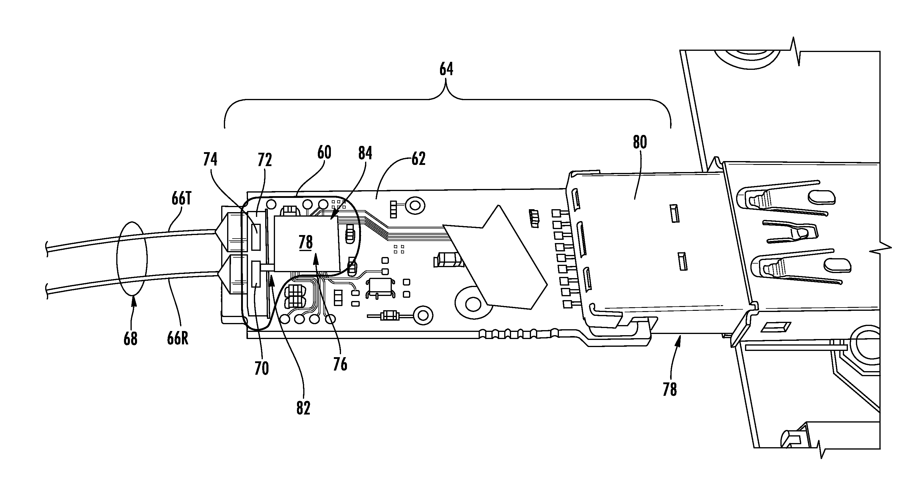
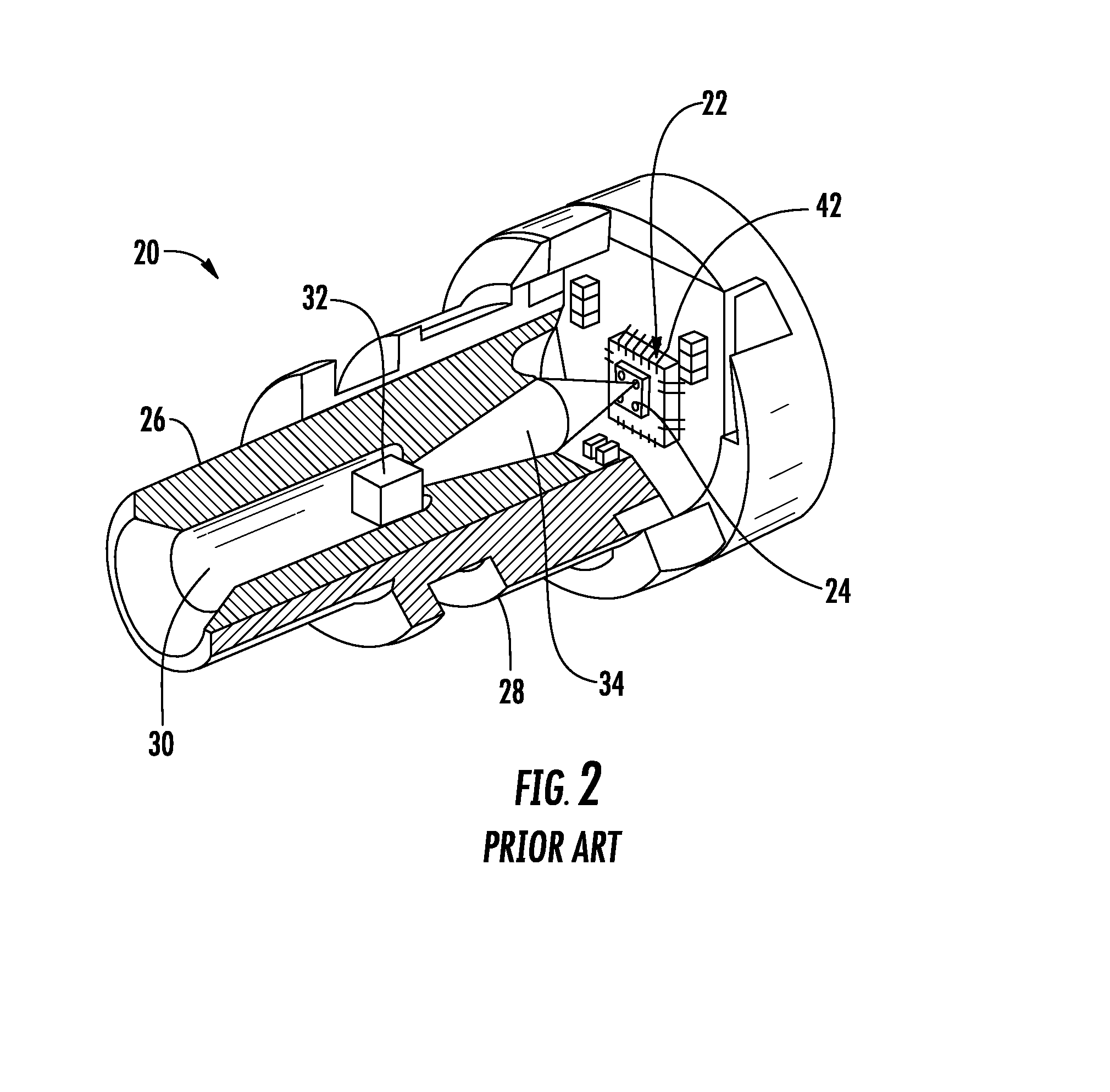
[0027]Embodiments disclosed herein include receiver optical assemblies (ROAs) having a photo-detector remotely located from transimpedance amplifier (TIA) that is suitable for short-haul applications. The TIA may be a complementary metal oxide semiconductor (CMOS)-based TIA in one non-limiting example. Related components, circuits, and methods are also disclosed. On the other hand, conventional long-haul ROSA designs have the photodiode intimately connected with the TIA and are not suitable for short-haul a...


PUM


Abstract

Embodiments disclosed herein include receiver optical assemblies (ROAs) having a photo-detector remotely located from a differential transimpedance amplifier (TIA). Related components, circuits, and methods are also disclosed. By providing the photo-detector remotely located from a TIA, additional costs associated with design constraints of providing the photo-detector intimate with a TIA may be avoided, thereby reducing cost of the ROA. In this regard as a non-limiting example, the ROAs according to the embodiments disclosed herein allow shorter haul active optical cable applications for use in consumer applications from a cost standpoint with the added benefits of increased bandwidth and low noise performance of optical fiber. In this regard, the ROAs disclosed herein provide higher input impedance differential TIA circuits and transmission circuits inhibiting or reducing ringing effects and maintain a sufficiently low resistance-capacitance (RC) time constant for differential TIA circuit to allow for higher bandwidth operation of the ROA.

Description

PRIORITY APPLICATIONS[0001]This patent application is a continuation-in-part application of U.S. patent application Ser. No. 13 / 790,350 filed on Mar. 8, 2013, the contents of which is relied upon and incorporated herein by reference in its entirety, and the benefit of priority under 35 U.S.C. §120 is hereby claimed.[0002]This patent application also claims priority to U.S. Provisional Application Ser. No. 61 / 716,868 filed on Oct. 22, 2012, the contents of which is relied upon and incorporated herein by reference in its entirety, and the benefit of priority under 35 U.S.C. §119 is hereby claimed.BACKGROUND[0003]1. Field of the Disclosure[0004]The technology of the disclosure relates to receiver optical assemblies (ROAs) that receive optical signals from an optical fiber and convert the received optical signals into electrical signals.[0005]2. Technical Background[0006]As interconnect line speeds increase, such as five (5) to ten (10) Gigabits per second (Gbps), and beyond, active opt...

Claims


Application Information

Patent Timeline
IPC IPC(8): G02B6/42H05K3/30
CPCH05K3/30G02B6/4295G02B6/4284G02B6/4279H04B10/69H05K1/0245H05K1/025H05K2201/10121Y10T29/49128
Inventor GALLOWAY, BRIAN JEFFREY
Owner CORNING OPTICAL COMM LLC
Why Eureka
Try Eureka