Device having an electrically heatable honeycomb body and method for operating the honeycomb body

a technology of electrical heat dissipation and honeycomb, which is applied in the direction of machine/engine, exhaust treatment electric control, separation process, etc., can solve the problem of relative fine insulating structur

Active Publication Date: 2014-04-24
EMITEC GESELLSCHAFT FUR EMISSIONSTECHNOLOGIE MBH
View PDF19 Cites 6 Cited by
  • Summary
  • Abstract
  • Description
  • Claims
  • Application Information

AI Technical Summary

Benefits of technology

[0009]In particular, at least one of these metallic foils is, as a current-conducting structure, embodied with insulation from adjacent metallic foils and has electrical contacts for connecting a voltage source outside the casing tube. In order to obtain a sufficient high electrical resistance in the current-conducting structure, the current-conducting structure preferably has a current path which is as long as possible, such as is achieved, for example, by a meandering shape. However, this results in relatively fine insulating structures. According to the invention, these are of such a size or are provided with such an insulating material that no electrical flashovers can occur when a voltage is applied of more than 24 V, in particular up to more than 48 V or even 60 V. This is achieved, in particular, by a gap size of at least 1 mm [millimeter].
[0011]In accordance with another preferred feature of the invention, the device has a control unit configured to generate a pulsed voltage and to apply that voltage to the current-conducting structure. Such a control unit makes it possible to feed the electrical power discontinuously to the current-conducting structure with the result that the energy supplied by the pulses can be adjusted by using the pulse width and / or the pulse repetition frequency. When such a control unit is used, current-conducting structures can also be operated with an on-board electrical system voltage of, for example, 48 V, although the current-conducting structures have not been originally configured for such high voltages. Given sufficiently short pulses and a suitably low repetition frequency, there is no risk of melting. Even arcing which possibly occurs when there is damage to the insulation is repeatedly quenched by the pulsed application of the voltage.
[0014]A pulsed voltage is understood to be a voltage which rises periodically between a zero voltage and a maximum voltage value and drops again. A pulsed voltage is preferably a rectangular-wave voltage or a sawtooth voltage. Due to the pulsed application of the electrical power to the current-conducting structure, energy is only discontinuously fed to the current-conducting structure with the result that the input of power can be kept in a desired range given a high maximum voltage even in current-conducting structures with a low resistance.
[0016]In accordance with a further mode of the invention, when a rectangular-wave voltage is applied it is preferred that each pulse has a pulse length of 0.001 s [second] to 1 s, particularly preferably of 0.005 s to 0.5 s. This makes it possible for the energy introduced into the current-conducting structure to be adapted by pulse width modulation.

Problems solved by technology

However, this results in relatively fine insulating structures.

Method used


Image

  • Device having an electrically heatable honeycomb body and method for operating the honeycomb body
  • Device having an electrically heatable honeycomb body and method for operating the honeycomb body
  • Device having an electrically heatable honeycomb body and method for operating the honeycomb body

Examples


Embodiment Construction

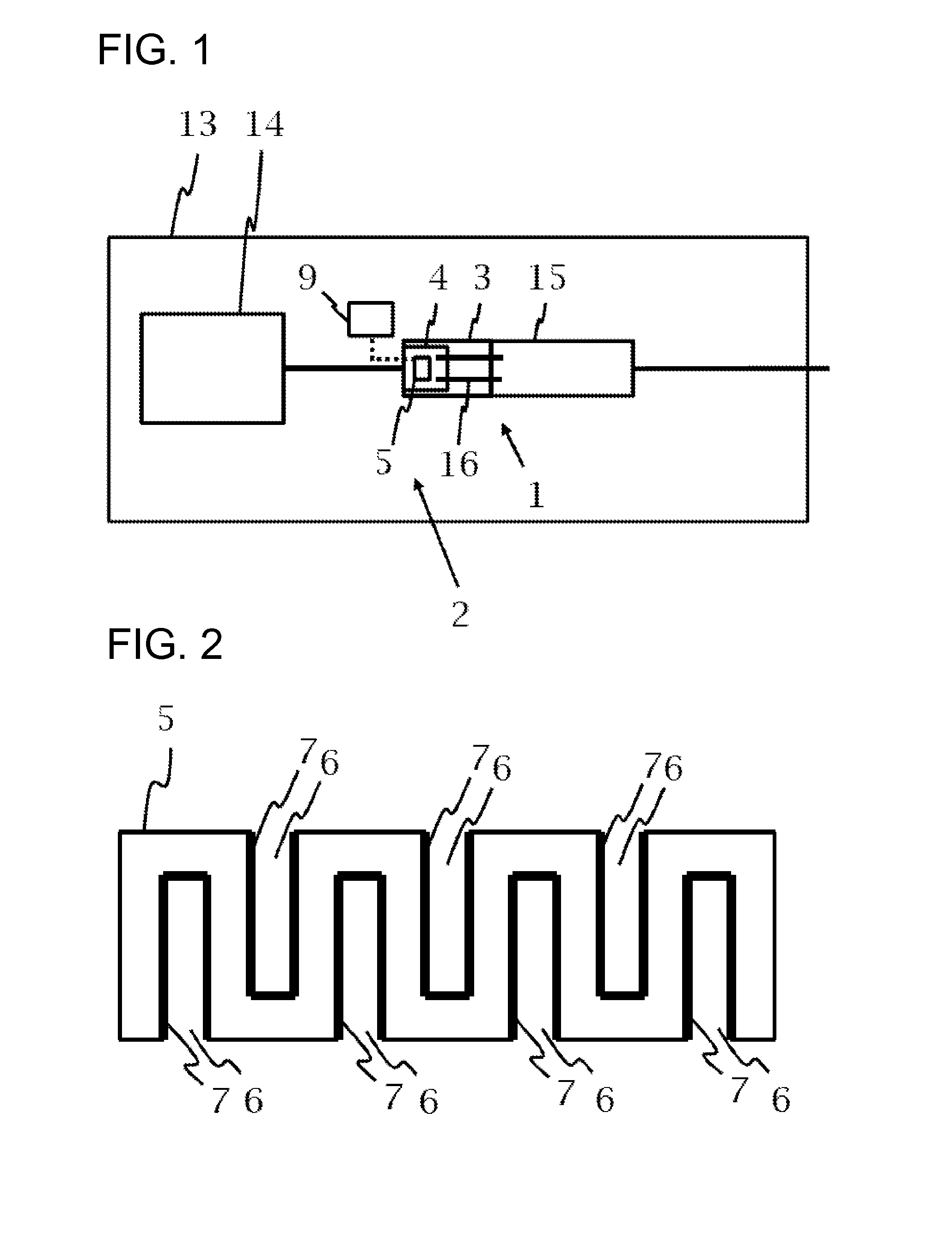
[0031]Referring now to the figures of the drawings in detail and first, particularly, to FIG. 1 thereof, there is seen a block diagram of a motor vehicle 13 having an internal combustion engine 14, an exhaust system 2 connected to the internal combustion engine 14 and a device 1 according to the invention disposed in the exhaust system 2. The device 1 includes a first honeycomb body 4 which is disposed in a casing tube 3 and in which a current-conducting structure 5 is formed. The current-conducting structure 5 is connected to a control unit 9. In addition, a second honeycomb body 15 is disposed in the casing tube 3. The first honeycomb body 4 and the second honeycomb body 15, which is disposed at a distance behind the latter, are connected through support elements 16 which project into the honeycomb bodies 4, 15 and which are disposed in sleeves in the first honeycomb body 4, with the intermediate positioning of electrical insulation.

[0032]As is seen in FIG. 2, the current-conducti...


PUM

PropertyMeasurementUnit
voltagesaaaaaaaaaa
voltagesaaaaaaaaaa
pulsed voltageaaaaaaaaaa

Abstract

A device for exhaust gas treatment in an exhaust system of an internal combustion engine, in particular in a motor vehicle, includes an electrically heatable honeycomb body through which an exhaust gas can flow. The honeycomb body is disposed in a casing tube and has at least one current-conducting structure with electric insulation for voltages greater than 24 V. A current-generating pulsed voltage is applied to the structure to heat the honeycomb body. It is thus possible for heating elements in the exhaust-gas flow to be powered by an on-board electrical system voltage of for example 48 V. A method for operating the honeycomb body is provided with which, even at operating voltages greater than 24 V, the generation of heat in the electrically heatable honeycomb body can be kept in a desired range by adjustment of a pulse width and / or repetition frequency of the pulsed voltage.

Description

CROSS-REFERENCE TO RELATED APPLICATION[0001]This is a continuation, under 35 U.S.C. §120, of copending International Application No. PCT / EP2012 / 061391, filed Jun. 15, 2012, which designated the United States; this application also claims the priority, under 35 U.S.C. §119, of German Patent Application DE 10 2011 104 193.5, filed Jun. 15, 2011; the prior applications are herewith incorporated by reference in their entirety.BACKGROUND OF THE INVENTIONField of the Invention[0002]The present invention relates to a device for catalytically converting, or otherwise treating, exhaust gases in an exhaust system, in particular in an exhaust gas purification system of a motor vehicle. The device has a honeycomb body which is disposed in a casing tube, can be heated electrically, and through which an exhaust gas can flow. The invention also relates to a method for operating such an electrically heatable honeycomb body. For this purpose, the honeycomb body has a current-conducting structure to ...

Claims


Application Information

Patent Timeline
Patent Type & Authority Applications(United States)
IPC IPC(8): F01N3/28B01D53/92
CPCB01D53/92F01N3/2889F01N9/00F01N2900/1404F01N3/2026Y02A50/20Y02T10/12Y02T10/40
Inventor HODGSON, JANVORSMANN, CHRISTIAN
Owner EMITEC GESELLSCHAFT FUR EMISSIONSTECHNOLOGIE MBH
Why Eureka
Try Eureka