Sensor integration in lateral flow immunoassays and its applications

a technology of lateral flow immunoassay and sensor, which is applied in the direction of measurement devices, instruments, scientific instruments, etc., can solve the problems of concave flow and artifacts in measurement, adversely affecting flow behavior, and unobstructed path for sample to flow rapidly down the edge of the membran

Active Publication Date: 2014-04-24
ROBERT BOSCH GMBH
View PDF5 Cites 14 Cited by
  • Summary
  • Abstract
  • Description
  • Claims
  • Application Information

AI Technical Summary

Problems solved by technology

With respect to the flow speed / rate damage to the membrane of the LFIA during the manufacturing process will introduce multiple artifacts that adversely affect the flow behavior.
For example, separation of the membrane from the backing (or adhesive tape) results in an unobstructed path for the sample to flow rapidly down the edge of the membrane.
This will lead to a concave flow and artifacts in the measurement.

Method used


Image

  • Sensor integration in lateral flow immunoassays and its applications
  • Sensor integration in lateral flow immunoassays and its applications
  • Sensor integration in lateral flow immunoassays and its applications

Examples


example 1

Flow Speed Sensor

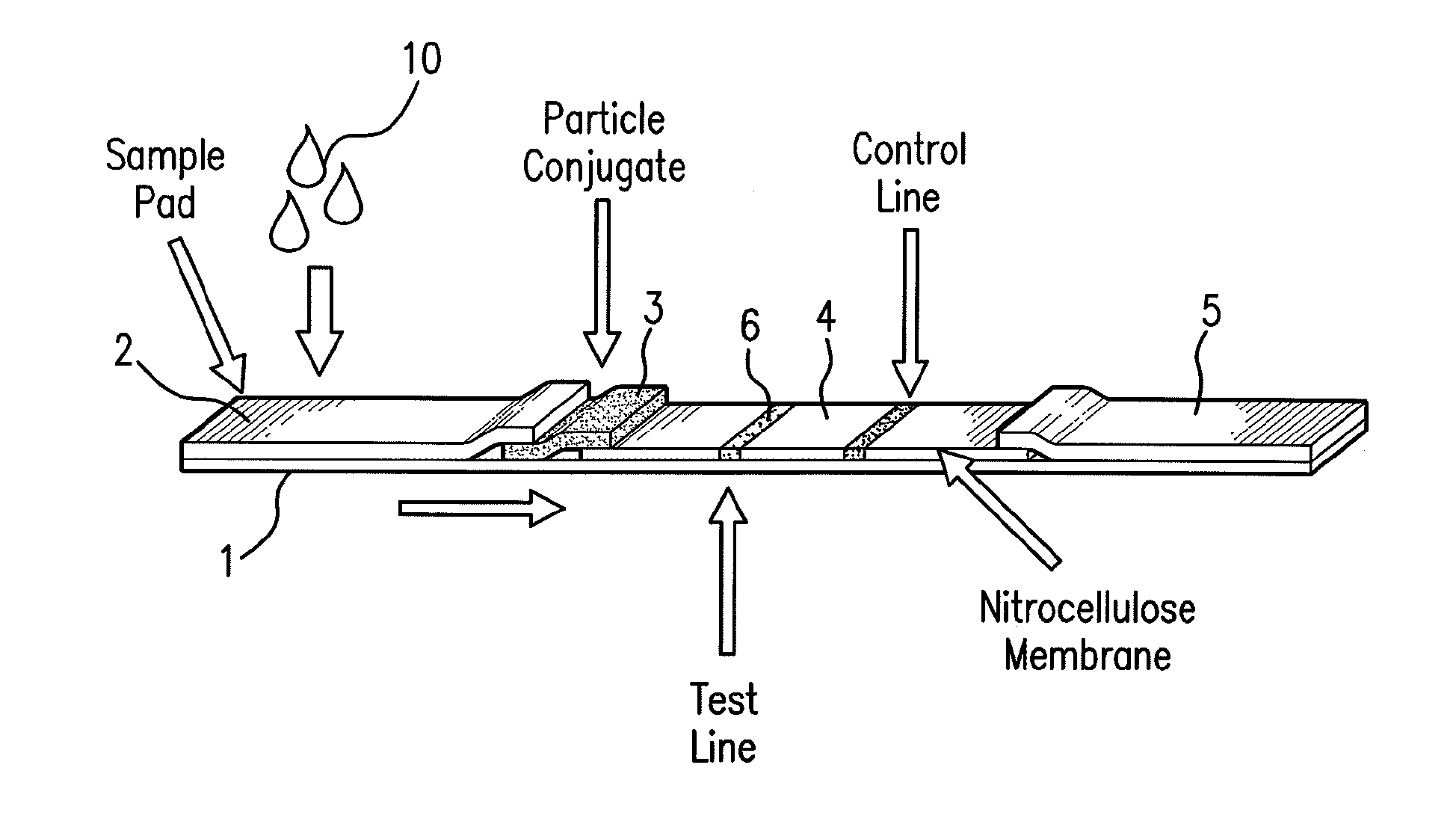
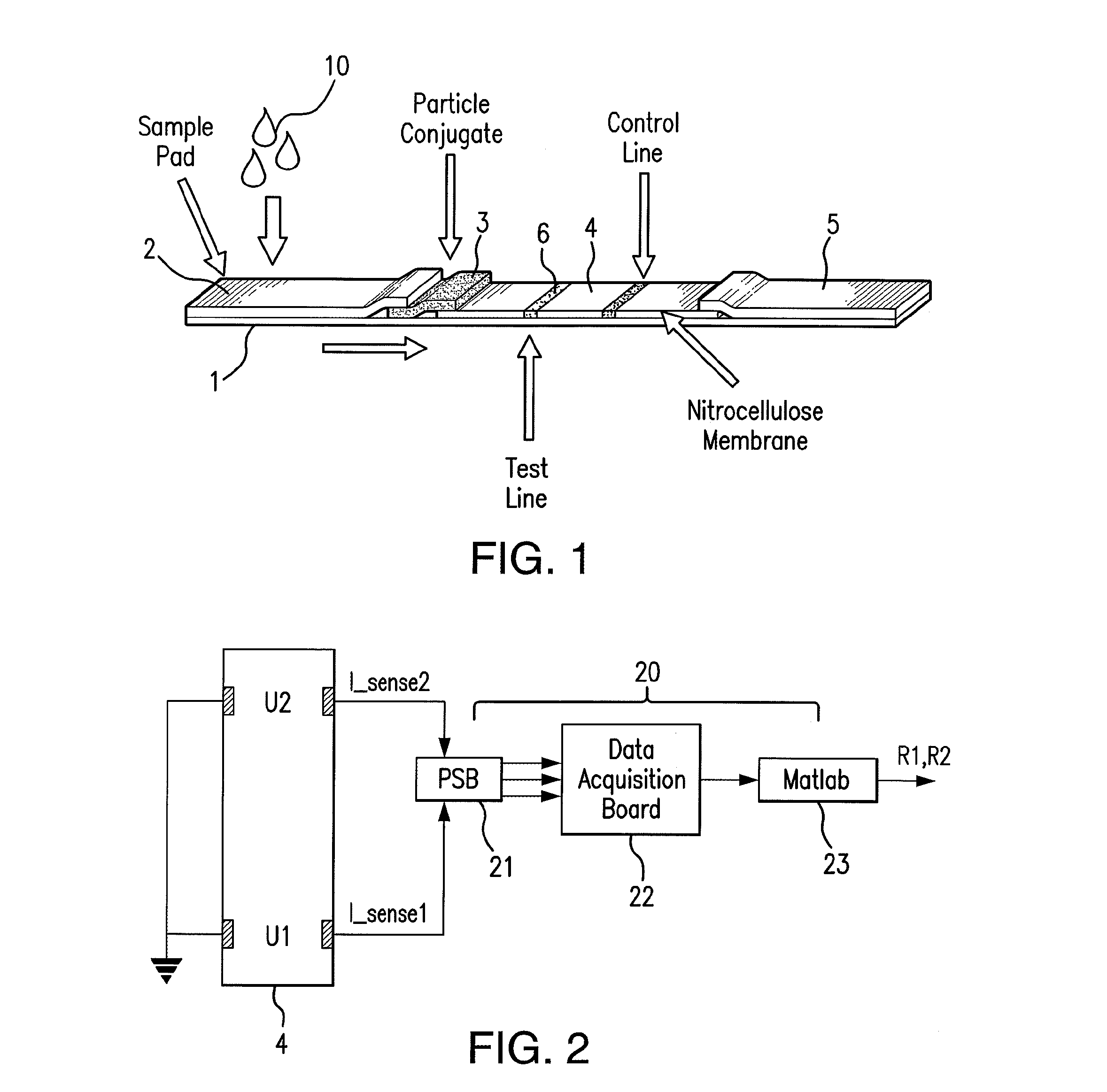
[0070]Conductive silver ink (DuPont 4929N) was applied to the treated nitrocellulose membrane using an art brush. The electrodes were connected to a printed circuit board (PCB) (see FIG. 2). A fixed voltage of v=1V was applied between each electrode pair and the corresponding current was measured by an instrumentation amplifier on the PCB. A Data Acquisition Board from National Instruments was used as the interface between the PCB and the computer (Matlab-Mathworks).

[0071]Two different solutions with different viscosities (PBS and Glycerol diluted in PBS 1:3) were applied to the sample pad of the LFIA. A solution of 1:3 PBS Glycerol decreases the flow speed to around ¼ of the flow speed measured with pure PBS solution.

[0072]To show the influence of wrong sample application on the flow speed a very low sample volume (500 μl) and a high sample volume (1000 μl) were compared with each other. The flow front of the low volume sample moved very slowly along the diagnostic...

example 2

Flow Shape Sensor

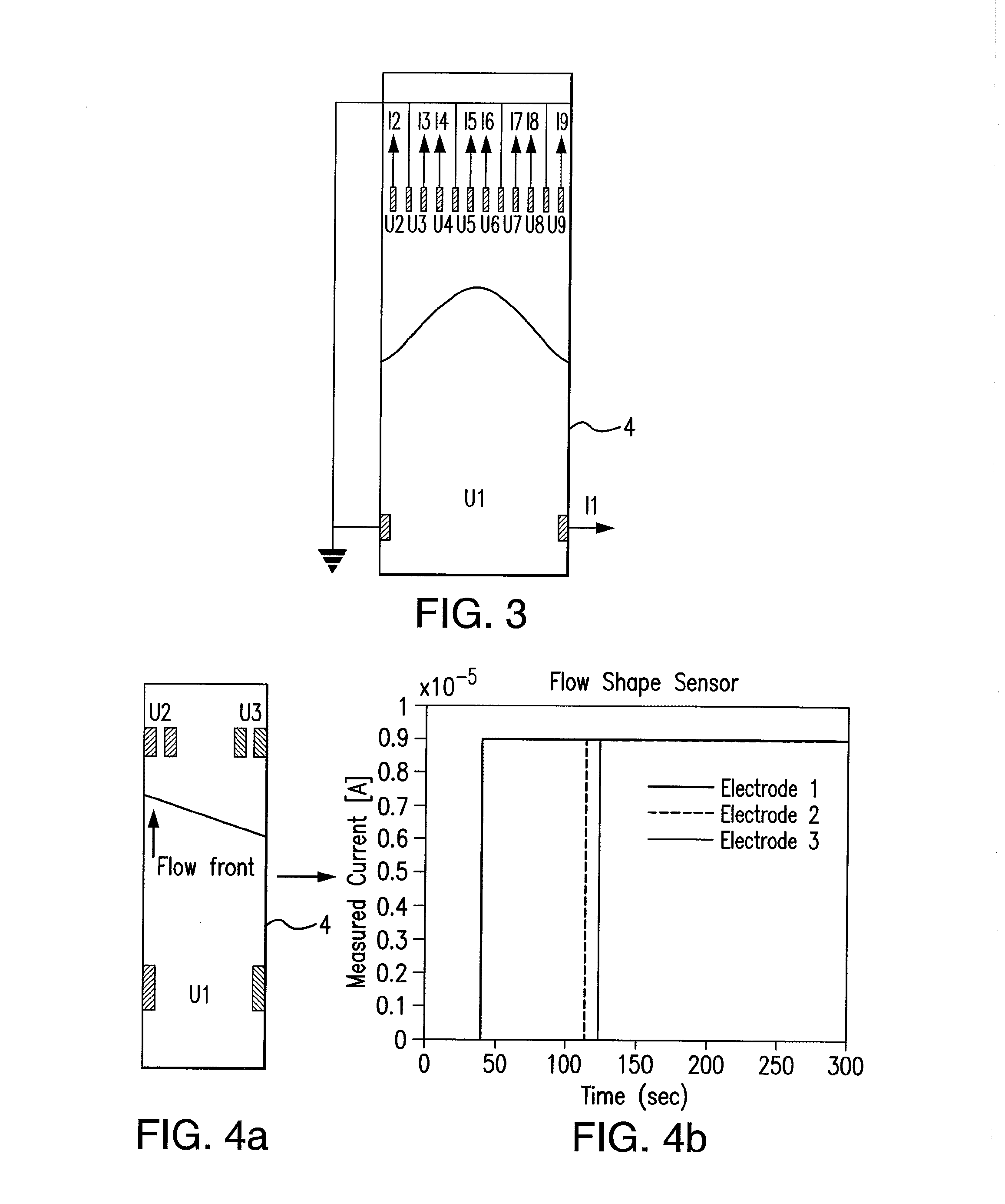
[0073]Conductive silver ink (DuPont 4292N) was applied to the treated nitrocellulose membrane using an art brush. The setup that was used is shown in FIG. 4a wherein multiple electrode pairs were applied to the treated nitrocellulose membrane. A non-uniform flow shape was created on purpose by applying a much larger amount of sample volume on the left side of the sample pad. The flow shape that was created looked similar to the one indicated in FIG. 4a. The results (after pulse removal) are shown in FIG. 4b. Due to the non-uniform flow front electrode 2 got shorted prior to electrode 3 being shorted.

example 3

Temperature Sensor

[0074]Conductive platinum ink (DuPont BQ321) was printed on the sample pad of the LFIA. The resistance was set to 110Ω at room temperature. The temperature of a hotplate was slowly increased to 100° C. An increase of the resistance was observed that was similar to a standard platinum Pt100 temperature sensor.


PUM

PropertyMeasurementUnit
volumeaaaaaaaaaa
volumeaaaaaaaaaa
resistanceaaaaaaaaaa

Abstract

Lateral flow immunoassay devices for determining the concentration of an analyte in a sample and methods for measuring analyte concentration in sample using such lateral flow immunoassay devices.

Description

FIELD OF THE INVENTION[0001]The invention relates to a device for Lateral Flow Immunoassays (LFAI's) as a biosensor, methods of improving such LFAI device, and using such LFAI device in a diagnostic method.BACKGROUND INFORMATION[0002]Recently there has been an increased interest in predictive, preventative, and particularly personalized medicine which requires diagnostic tests with higher fidelity, e.g., sensitivity and specificity. Lateral Flow Immunoassay (LFIA) devices incorporate such diagnostic test and is a well-established technology in Point-of-Care (POC) diagnostics. Low cost, relative ease of manufacture, long shelf life, and ease of use by the customer are some of the advantages that make LFIA's very attractive.[0003]The basic principal of a Lateral Flow Immunoassay is shown in FIG. 1. During the early development of LFIA diagnostic devices, the main focus was primarily on qualitative systems which provide an easy yes or no answer. The best know qualitative lateral flow s...

Claims


Application Information

Patent Timeline
Patent Type & Authority Applications(United States)
IPC IPC(8): G01N33/53
CPCG01N33/5302G01N33/54366G01N33/561
Inventor KAVUSI, SAMKOTZ, FREDERIK
Owner ROBERT BOSCH GMBH
Why Eureka
Try Eureka