Method for generating data in storage system having compression function

Active Publication Date: 2014-04-24
HITACHI LTD
View PDF3 Cites 15 Cited by
  • Summary
  • Abstract
  • Description
  • Claims
  • Application Information

AI Technical Summary

Benefits of technology

The present invention improves the performance of reading and writing data that has been compressed by reducing unnecessary decompression processing based on the relationship between the read / write request range and the compression unit.

Problems solved by technology

First, the deduplication function of a storage system generally detects duplicated data in file units or specific data length units, and reduces the amount of data by not storing duplicated data.
On the other hand, the demerit of such function is the deterioration of access performance to the data.
Especially in the compression function, when a data read request targeting compressed data is received, the data must be decompressed via compression units, according to which the data read performance is deteriorated due to overhead of de-compression processing.
Therefore, the update performance is deteriorated due to the overhead of the decompression processing and the compression processing.

Method used


Image

  • Method for generating data in storage system having compression function
  • Method for generating data in storage system having compression function
  • Method for generating data in storage system having compression function

Examples


embodiment 1

[0042]Now, the first embodiment of the present embodiment will be described with reference to FIGS. 1 through 12.

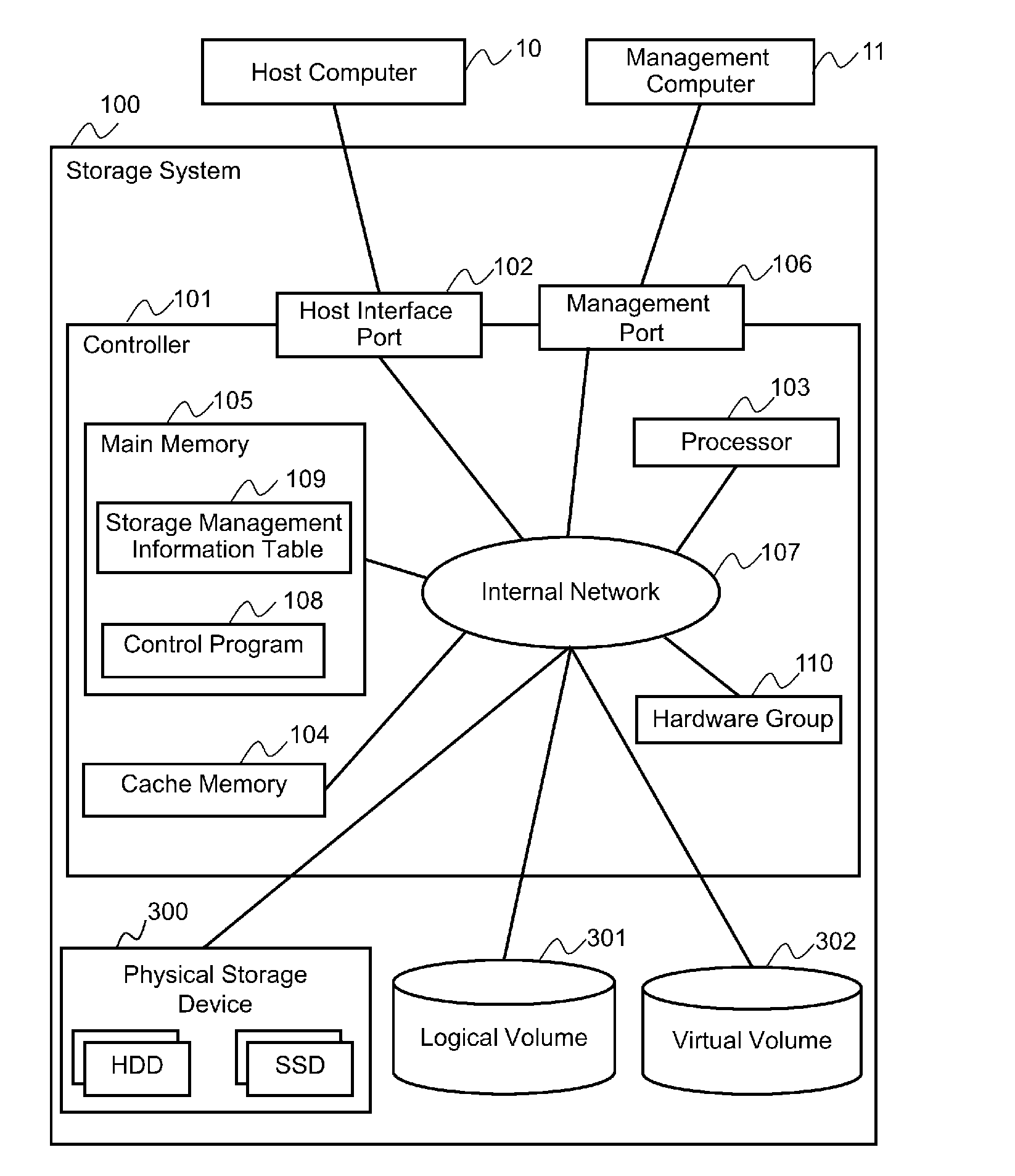
[0043]FIG. 1 is a block diagram illustrating a configuration example of a storage system according to embodiment 1.

[0044]A storage system 100 is composed of one or more controllers 101 for controlling the storage system 100, one or more host interface ports 102 for performing transmission and reception of data with a host computer 10, one or more processors 103, one or more cache memories 104, one or more main memories 105, one or more management ports 106 for connecting a management computer 11 for managing the storage system 100 and the storage system 100, a logical volume 301 or a virtual volume 302 for storing user data and the like, a hardware group 110 for performing parity calculation and other various computation processing, and an internal network 107 for mutually connecting components such as the processor 103 and the cache memory 104. Computation processing suc...

embodiment 2

[0073]Now, embodiment 2 of the present invention will be described with reference to FIGS. 13 through 22. In embodiment 2, the method for solving pattern B and pattern C that cannot be solved by embodiment 1 will be described. The details of the present embodiment will now be illustrated.

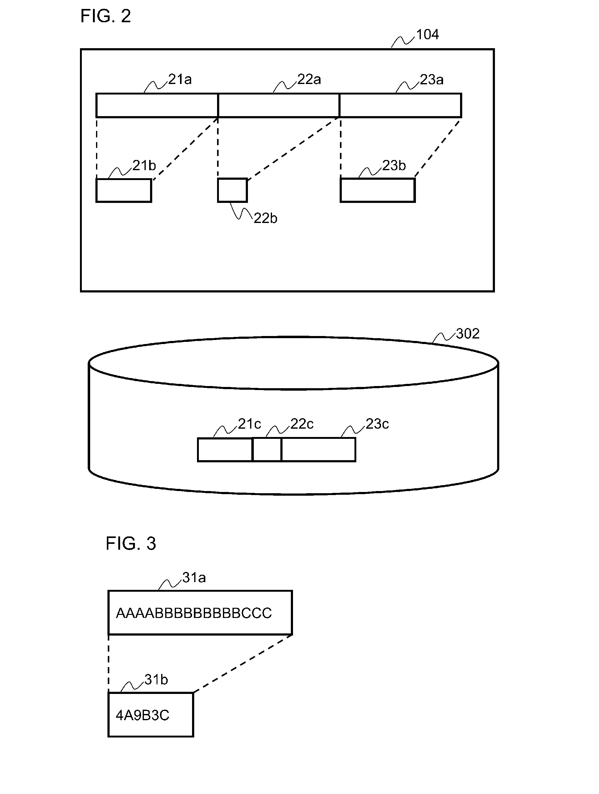
[0074]FIG. 13 is a view showing one example of the concept of compression processing according to embodiment 2. In embodiment 1, the run-length compression algorithm has been illustrated as a typical example of a common compression algorithm, and embodiment 2 will also be described taking the run-length compression algorithm as the example. In a common run-length compression algorithm, the compression target data is searched from the beginning to detect successive data, and the successive data is replaced with length information in order to compress data. In embodiment 2, to cope with pattern C, the non-compressed data 31a being the target of compression is divided at intermediate point 32t, wherein...

embodiment 3

[0090]Now, the third embodiment of the present invention will be described with reference to FIGS. 23 through 25. In the third embodiment, a method described in embodiment 2in which the decompression range boundary can be varied will be described.

[0091]FIG. 23 is a view showing a decompression boundary management table 122 according to embodiment 3. The decompression boundary management table 122 is stored in the main memory 105. The decompression boundary management table 122 is a table composed of the following items: an LBA 1211, a compression method 1215, and a decompression boundary 1221. The LBA 1211 and the compression method 1215 are the same as those in the compression address management table 121. The decompression boundary 1221 denotes an offset address of the decompression range boundary of the relevant compression unit. For example, if the decompression boundary 1221 is set to 128 KB, it means that the decompression range boundary of the relevant compression unit is at ...


PUM


Abstract

The present invention aims at improving the performance of a compression function in a storage system, and solves the prior art problem of having to decompress a whole compression unit even if a read request or a write request targets only a portion smaller than the compression unit, causing increase of overhead of decompression processing and elongation of processing time, and deteriorating performance The present invention prevents unnecessary decompression processing and reduces the overhead of processing by suppressing the range of decompression processing to a minimum portion according to the relationship between the read / write request range and the compression unit.

Description

TECHNICAL FIELD[0001]The present invention relates to an art for improving the access performance to compressed data in a storage system having a function to compress and store data.BACKGROUND ART[0002]The amount of data generated in companies or by individuals is rapidly increasing year by year. Especially in companies, there are demands to cut down costs related to media for storing confidential data and other data safely or to cut down management costs.[0003]Some storage systems are provided with a deduplication function or a compression function as functions for cutting down the actual amount of stored data itself. First, the deduplication function of a storage system generally detects duplicated data in file units or specific data length units, and reduces the amount of data by not storing duplicated data. Such deduplication function is considered to be effective for storage systems used for backup purposes based on such characteristics. Further, the compression function of a s...

Claims


Application Information

Patent Timeline
IPC IPC(8): G06F17/30
CPCG06F3/0608G06F3/0685G06F3/064G06F17/30153G06F16/1744
Inventor ARAKI, AKIHIKOYAMAMOTO, AKIRASHIGA, KENTA
Owner HITACHI LTD
Why Eureka
Try Eureka