Systems and Methods to Determine the Condition of a Battery

a battery and condition technology, applied in secondary cell servicing/maintenance, instruments, manufacturing tools, etc., can solve the problems of not directly measuring coulomb counting has the disadvantage of not being able to accurately measure the energy in the battery, and cranking test has the disadvantage of requiring a controlled temperatur

Active Publication Date: 2014-05-01
BAYERISCHE MOTOREN WERKE AG
View PDF0 Cites 21 Cited by
  • Summary
  • Abstract
  • Description
  • Claims
  • Application Information

AI Technical Summary

Benefits of technology

[0010]As yet another alternative, the method may include measuring a current of the battery over time while discharging the battery, wherein the slope is calculated based on the terminal voltage and the current of the battery at three or more data points. The slope may be calculated based on a discrete matrix representation.

Problems solved by technology

However, voltage sensing has the disadvantages that each voltage discharge curve is unique, and that the voltage discharge curve changes as the battery ages.
However, coulomb counting has the disadvantages of not directly measuring the energy in the battery, and assuming an initial value of charge in the fully charged battery based on Peukert's law.
However, the cranking test has the disadvantage of requiring a controlled temperature.
However, the AC conductance test has the disadvantages that repeated tests are needed at multiple frequencies, and the accuracy is diminished when testing more than one battery.
However, EIS has the disadvantages of requiring expensive equipment, as well as training to interpret the results.

Method used


Image

  • Systems and Methods to Determine the Condition of a Battery
  • Systems and Methods to Determine the Condition of a Battery
  • Systems and Methods to Determine the Condition of a Battery

Examples


first embodiment

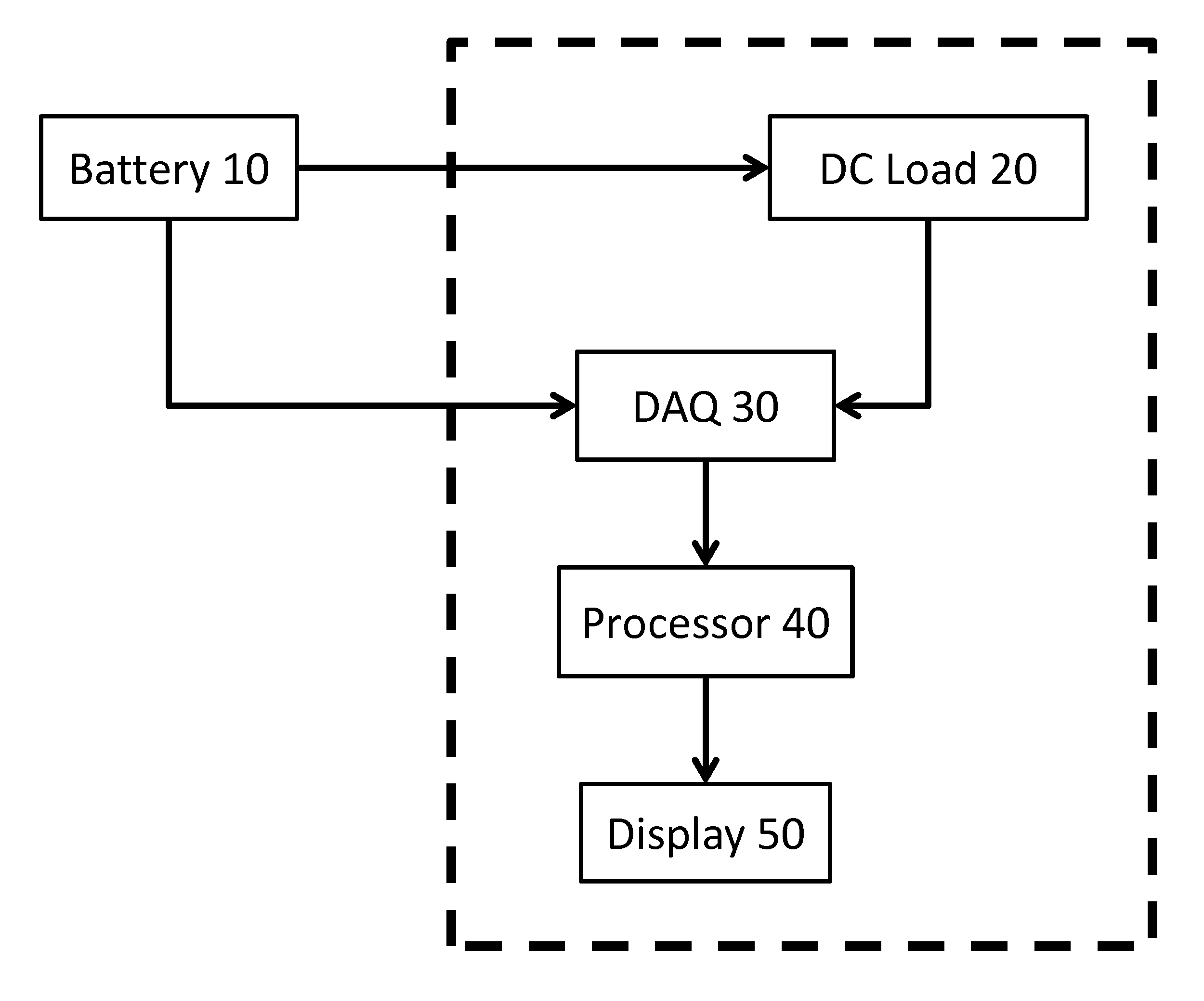
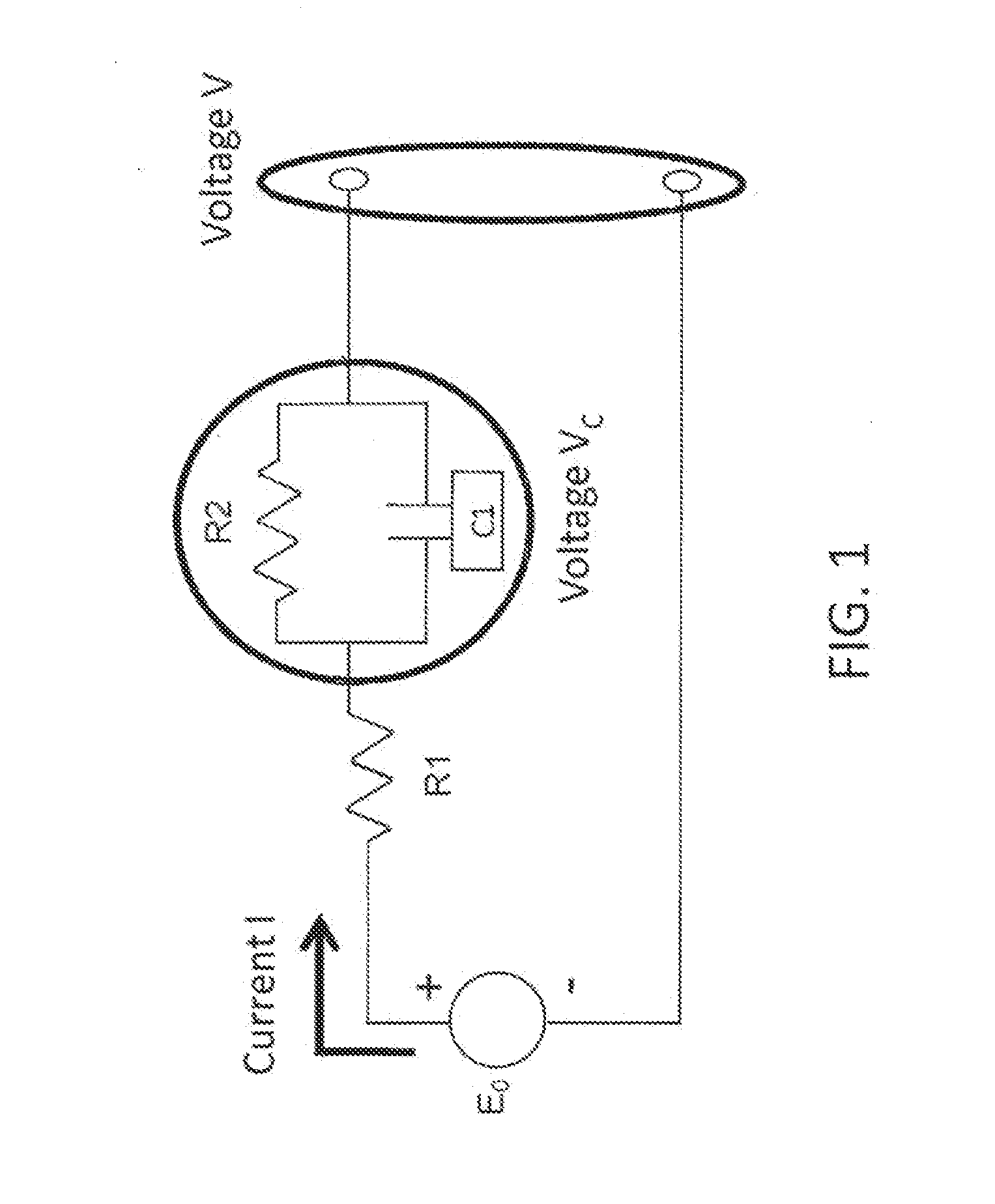
[0041]FIG. 5 shows how to calculate the slope of the natural logarithm of the rate of change of the voltage VC according to various embodiments of the present invention. The measured terminal voltage V is annotated and shown as a function of time in FIG. 5. In a first embodiment, the processor 40 calculates the voltage VC as a function of time based on Equation (1). The open circuit voltage E0 is measured before the DC load 20 starts drawing current from the battery 10, the current I is measured while the battery 10 discharges, and the resistance R is calculated according to:

R=E0-V2IEquation(4)

where V2 is a voltage measured immediately after the DC load 20 starts drawing current from the battery 10 but before the terminal voltage V begins to curve. As shown in FIG. 5, V2 may be the voltage measured at the first data point after the DC load 20 starts drawing current from the battery 10. For example, V2 would be approximately 12.6 V based on the terminal voltage curve shown in FIG. 5....

second embodiment

[0043]The slope may be calculated by any appropriate method. For example, in a second embodiment, the processor 40 calculates the slope based on characteristics of the measured terminal voltage V. According to the right-hand side of Equation (3), the slope of the natural logarithm of dVc / dt may be expressed as −1 / R0C. R0 may be calculated according to:

R0=V2-V3IEquation(5)

where V3 is a voltage measured after the discharge from the capacitor C1 has stabilized. V3 may be estimated visually or by using the processor 40 to apply thresholds that account for noise in the measurements. For example, the processor 40 may select V3 when the voltage difference between successive data points is less than 0.01 V. In the example shown in FIG. 5, V3 is approximately 12.325 V. C may then be calculated according to:

C=t3-t24R0Equation(6)

where t3 and t2 are the times at which the voltages V3 and V2 were measured, respectively, as shown in FIG. 5. The slope is then calculated as −1 / R0C.

third embodiment

[0044] the slope may be calculated by using a discrete matrix representation of the system. In this approach, R, R0, and C are unknown parameters that are determined based on the measured terminal voltage V shown in FIG. 5 and a generalized inverse matrix. Equation (1) may be discretized and rewritten as:

VC(k)=E0−R*I(k)−V(k)  Equation (7)

where k is an index of the dataset. Further, Equation (3) may be discretized and rewritten as:

R0C[VC(k+1)-VC(k)T]+VC(k)=I(k)R0Equation(8)

where T is the sampling rate. In this embodiment, both the terminal voltage V and the current I are measured as functions of time. The system may be represented by the following matrices:

[-I(k+1)+I(k)-V(k+1)+V(k)-I(k)] [R0RCR0CT(R0+R)]=-T[E0-V(k)]Equation(9)

This yields three equations having three unknowns, namely R, R0, and C. Equation (9) may then be used to solve for R, R0, and C, and the slope is again calculated according to −1 / R0C. At least three data points are required to determine R, R0, and C; however, an...


PUM

PropertyMeasurementUnit
temperaturesaaaaaaaaaa
terminal voltageaaaaaaaaaa
threshold slopeaaaaaaaaaa

Abstract

Systems and methods for determining the damage level of a battery are provided. An exemplary method includes measuring a terminal voltage of the battery over time while discharging the battery at a predetermined current; calculating a slope of a natural logarithm of a rate of change of a first voltage of the battery over time based on the terminal voltage of the battery; and comparing the calculated slope to a threshold slope that is based on measurements of a plurality of similar batteries with known conditions. The first voltage of the battery may correspond to a voltage across an RC component of an equivalent circuit model for the battery.

Description

BACKGROUND OF THE INVENTION[0001]The present invention relates to systems and methods for determining the condition of a battery, such as a damage level of the battery.[0002]There are several related art technologies for evaluating different aspects of the condition of a battery. For example, voltage sensing establishes a predicted voltage discharge curve for the battery with the voltage as a function of the state of charge (SOC), measures the voltage between the terminals of the battery, and compares the measured voltage to the predicted voltage discharge curve to determine the SOC of the battery. However, voltage sensing has the disadvantages that each voltage discharge curve is unique, and that the voltage discharge curve changes as the battery ages.[0003]Another technique is known as coulomb counting, in which the remaining capacity of the battery is determined by measuring the current entering or leaving the battery, and integrating this measurement over time. The current may b...

Claims


Application Information

Patent Timeline
Patent Type & Authority Applications(United States)
IPC IPC(8): G06F19/00B23P11/00B23P17/00G06F17/16
CPCG01R19/12G01R31/3842H01M10/42Y02E60/10Y10T29/49764Y10T29/49771
Inventor PISU, PIERLUIGIVENHOVENS, PAULMOHON, SARASTREIT, JAMES WILLIAM
Owner BAYERISCHE MOTOREN WERKE AG
Why Eureka
Try Eureka