
Color filter substrate having touch-sensing function

a color filter substrate and touch sensing technology, applied in the field of color filter substrates, can solve the problems of strict limitation of the original thickness and weight of the final product, and achieve the effect of reducing the overall thickness and weight of the product, and eliminating the fabrication process

Inactive Publication Date: 2014-05-01
WINTEK CORP
View PDF7 Cites 21 Cited by
  • Summary
  • Abstract
  • Description
  • Claims
  • Application Information

AI Technical Summary

Benefits of technology

This patent text describes a color filter substrate that has the added benefit of being a touch-sensing display. By integrating touch-sensing functions into the patterned common electrode layer of the color filter substrate, the overall thickness and weight of the touch display panel is reduced, along with lower fabrication costs. Additionally, this design eliminates the need for an additional touch panel, thereby further reducing thickness and weight of the product.

Problems solved by technology

However, the integration of display panel and touch panel typically involves finishing the production of each unit separately before uniting them together, resulting that the thickness and weight of the final product is strictly limited to the original thickness and weight of each individual unit.

Method used


Image

  • Color filter substrate having touch-sensing function
  • Color filter substrate having touch-sensing function
  • Color filter substrate having touch-sensing function

Examples


first embodiment

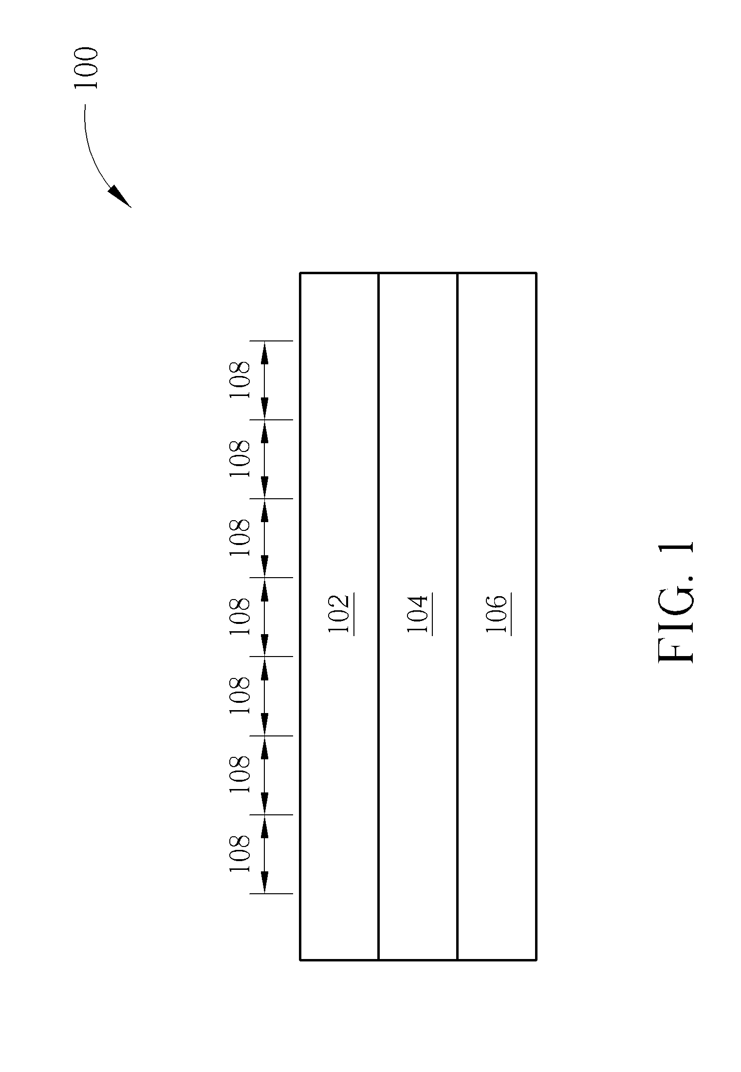
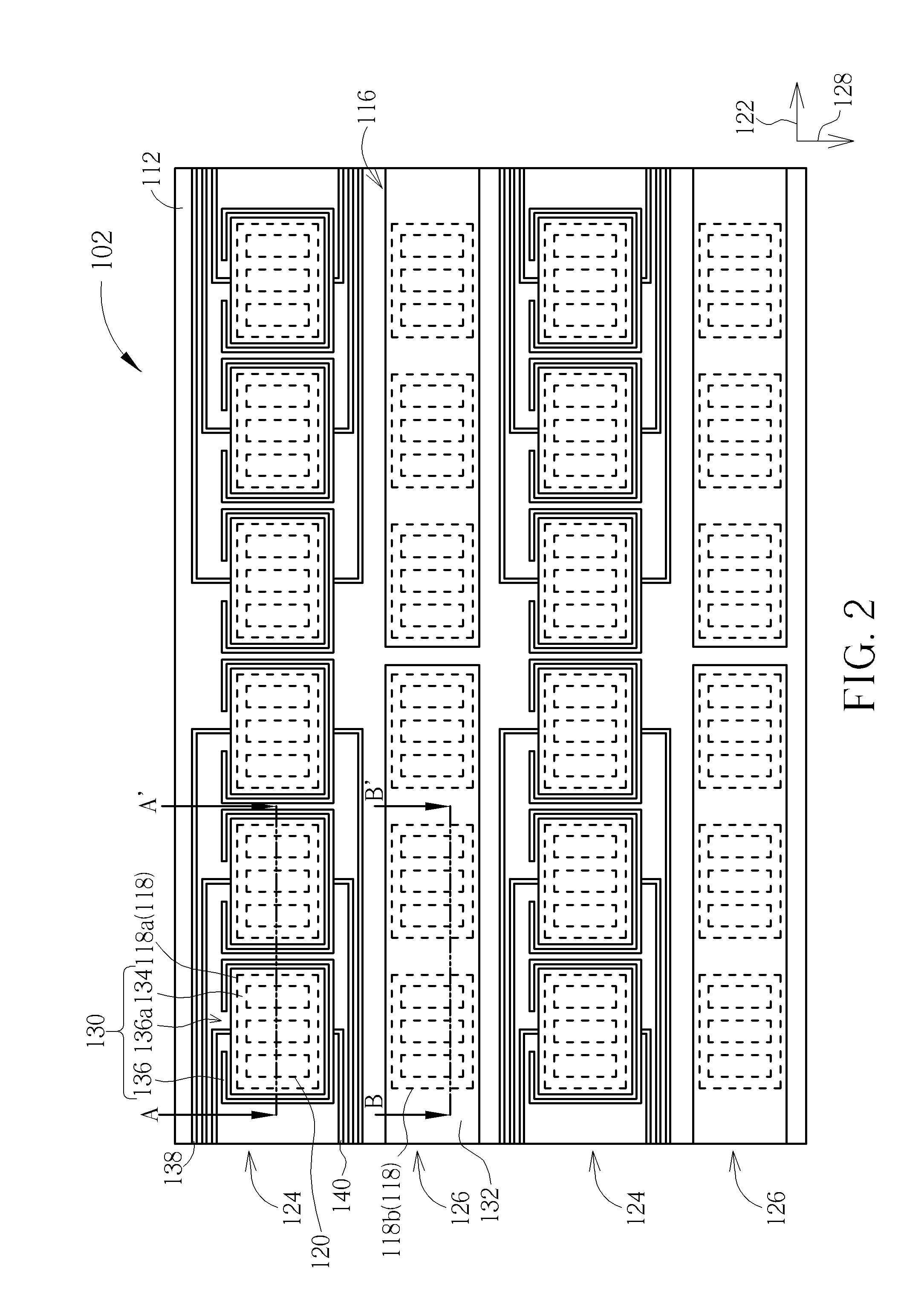
[0020]An embodiment with color filter substrate having touch-sensing function and touch display panel 100 being a liquid crystal display penal is explained below, but not limited therein. Referring to FIGS. 2-4 and FIG. 1, FIG. 2 illustrates a top view of a color filter substrate with touch-sensing function according to the present invention and FIGS. 3-4 are cross-sectional views of FIG. 2 along the sectional lines AA′ and BB′. As shown in FIGS. 1-4, the color filter substrate 102 having touch-sensing function includes a substrate 110, a black matrix 112, a plurality of color filters 114, and a patterned common electrode layer 116. The substrate 110 has a plurality of pixel regions 118 arranged as a matrix, in which the pixel regions 118 are situated corresponding to the pixel regions 108 of the touch display panel 100 and each pixel region 118 includes a plurality of sub-pixel regions 120. The black matrix 112 is situated on one side of the substrate 110 opposite to the array subs...

second embodiment

[0029]Referring to FIG. 6, FIG. 6 illustrates a cross-sectional view of a color filter substrate with touch-sensing function according to the present invention. As shown in FIG. 6, the color filter substrate 200 does not include a planarization layer, so that the patterned common electrode layer 202 is situated directly on the color filters 114 and the black matrix 112.

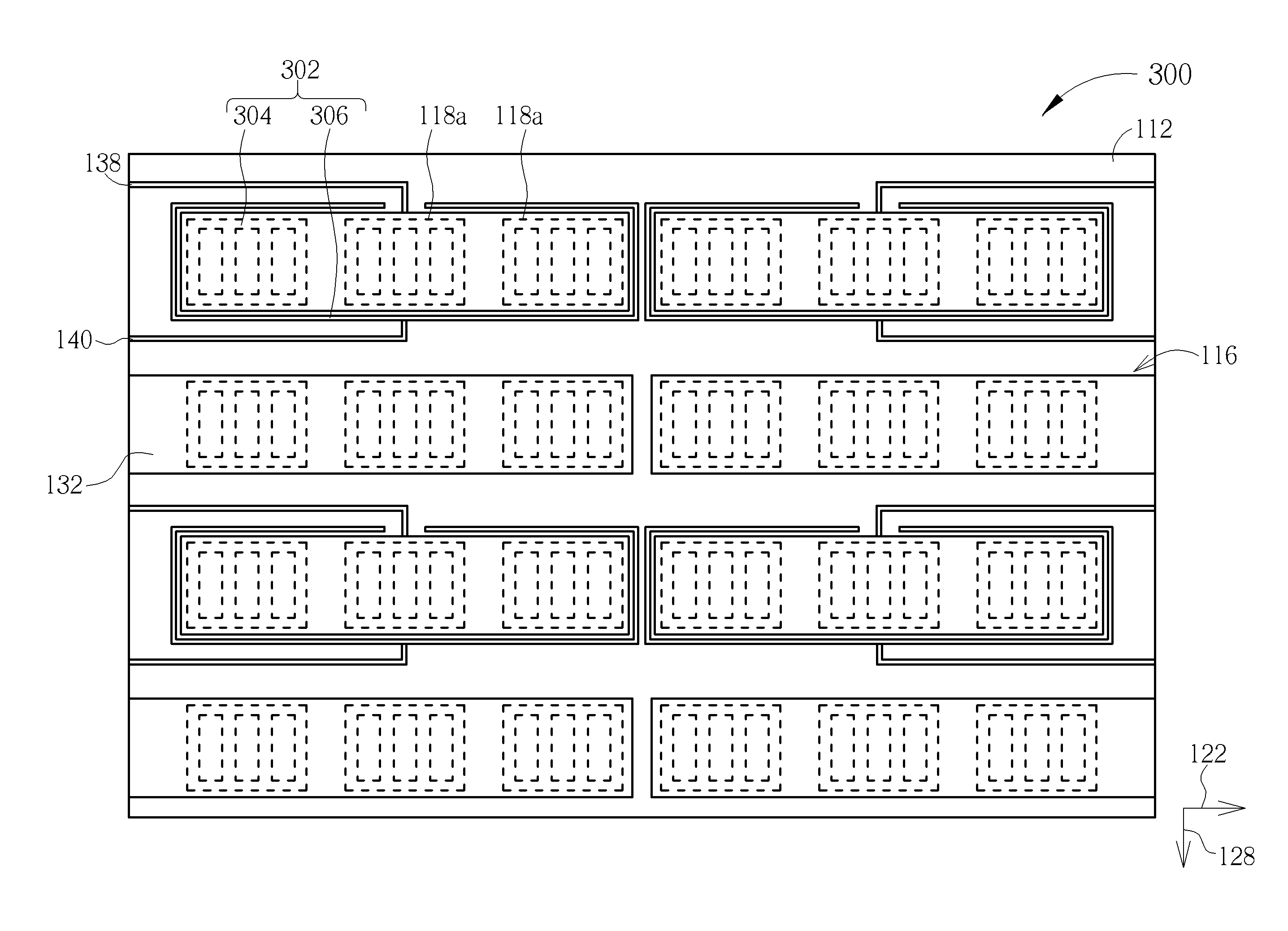
[0030]Referring to FIG. 7, FIG. 7 illustrates a top view of a color filter substrate with touch-sensing function according to a third embodiment of the present invention. As shown in FIG. 7, as compared with the first embodiment, the integrated units 302 of the color filter substrate 300 in this embodiment are placed corresponding to a plurality of first pixel regions 118a, in which the signal transmitting electrodes 304 are disposed to cover the first openings 112a of the firs pixel regions 118a. The signal receiving electrodes 306 are placed to partially surround the signal transmitting electrodes 304. For instance,...


PUM


Abstract

The present invention provides a color filter substrate with a touch-sensing function including a substrate, a black matrix, a plurality of color filters, and a patterned common electrode layer. The substrate has a plurality of pixel regions arranged as a matrix, and each pixel region includes a plurality of sub-pixel regions. The black matrix is disposed on the substrate, and has a plurality of openings exposing the substrate and corresponding to each sub-pixel region respectively. Each color filter covers the substrate exposed by each opening. The patterned common electrode layer is disposed on the black matrix and the color filters, and the patterned common electrode layer includes a plurality of integrated units respectively configured for touch sensing and transferring a common signal.

Description

BACKGROUND OF THE INVENTION[0001]1. Field of the Invention[0002]The invention relates to a color filter substrate, and more particularly to a color filter substrate having touch-sensing function.[0003]2. Description of the Prior Art[0004]Having man-machine interactive feature, touch panels have been widely used in input interface of various instruments. As application of consumer electronic products developed broadly in recent years, the products applying the touch display panel integrated with the touch panel and displays are increased, such as mobile phones, GPS navigation systems, tablet PCs, PDAs, and laptop PCs. Common technology involves integrating touch panels and liquid crystal display panels to form touch liquid crystal display panels. However, the integration of display panel and touch panel typically involves finishing the production of each unit separately before uniting them together, resulting that the thickness and weight of the final product is strictly limited to t...

Claims


Application Information

Patent Timeline
Patent Type & Authority Applications(United States)
IPC IPC(8): G09G3/20
CPCG09G3/2003G02F1/133514G06F3/0412G06F3/0443G06F3/0448
Inventor WU, YI-CHUNLIU, YU-CHENSHIE, WUN-YI
Owner WINTEK CORP
Learn More