
Ultrasonically heated probe

a probe and ultrasonic technology, applied in the field of ultrasonic probes, can solve the problems of increased skin tissue, wrinkles and sagging skin, and not desirable aesthetic conditions

Inactive Publication Date: 2014-05-01
SOLTA MEDICAL
View PDF0 Cites 164 Cited by
  • Summary
  • Abstract
  • Description
  • Claims
  • Application Information

AI Technical Summary

Benefits of technology

The patent text discusses different approaches to remove fat cells using ultrasound and laser technology. However, some of these methods have drawbacks, such as potential tissue damage and high temperatures. The technical effect of the patent is to provide a new approach that overcomes these drawbacks and provides a safer and more efficient way to remove fat cells.

Problems solved by technology

As people age, there may be an increase in skin tissue laxity, leading to wrinkles and sagging skin.
These are not desirable aesthetic conditions.
In this case, the removal of the underlying fat can cause the overlying skin to appear saggy.
These two desires are often in conflict in practice.
When collagen fibers are subjected to heating, their highly oriented structure is denatured or transformed into an amorphous state, with the net result of tissue shrinkage.
When collagen denatures, it shrinks, thus causing a tightening of the tissue.
There are problems with the current approaches, however.
The radiofrequency (“RF”) approach can be applied externally, but the energy density required to cause contraction of the underlying collagen matrix may also cause damage to the overlying skin.
A similar issue occurs with laser treatment.
While an externally focused ultrasound approach does cause tissue necrosis, remodeling, and contraction, it is limited to a relatively small area such as the eyebrows, and cannot be used over a large area, for instance, over the buttocks.
This two-step approach is cumbersome, requiring two completely different surgical energy devices.
While these are non-invasive approaches, they involve energy transmission through skin and other tissues that should not be heated.
Because of this, these treatments are limited with regard to the area treated and the speed of treatment.
Again, the heating is limited because the skin surface should not be heated.
However, it can easily reach high temperatures, beyond those required to denature collagen, and thereby can cause unwanted tissue damage.
By moving the tip around within the tissue, an appropriate average temperature rise can be accomplished; however, there is little or no direct control over the distribution of energy within the tissue.

Method used


Image

  • Ultrasonically heated probe
  • Ultrasonically heated probe
  • Ultrasonically heated probe

Examples


Embodiment Construction

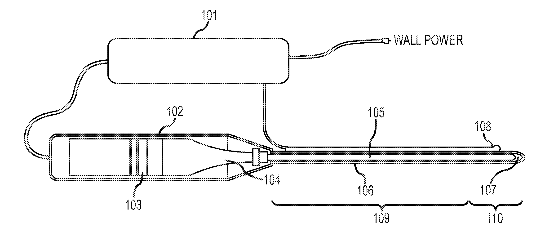
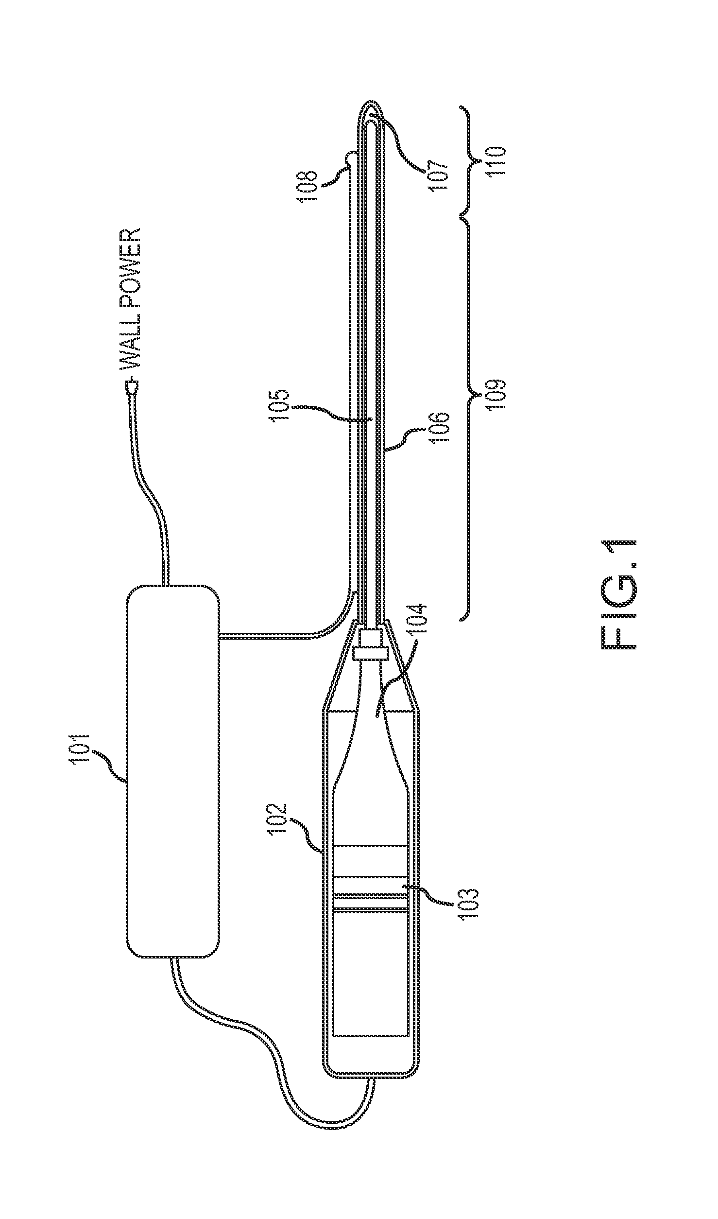
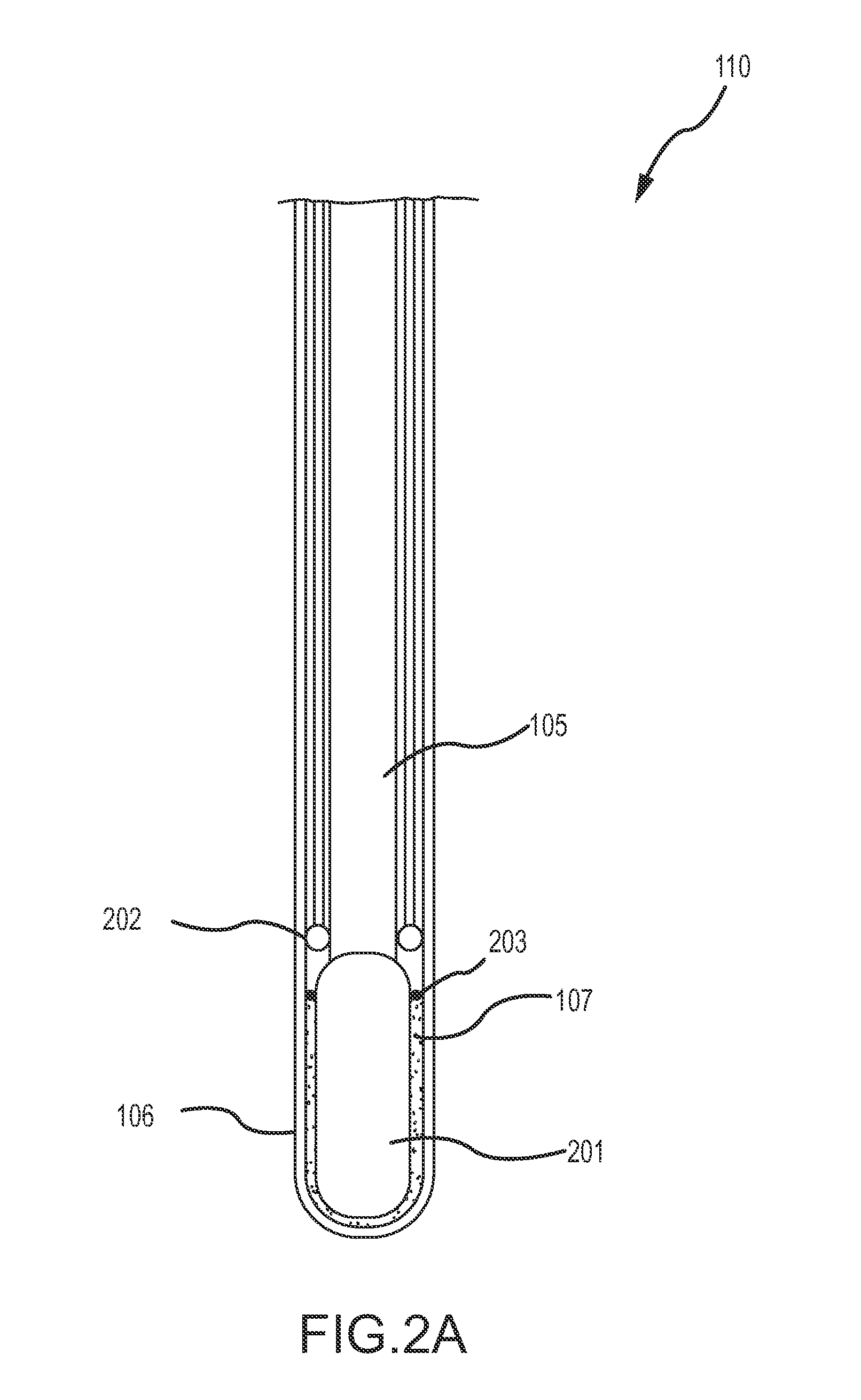
[0021]FIG. 1 is an overall diagram of a tissue heating apparatus, including a driver assembly comprising a generator 101 of high-energy electrical signals in the ultrasonic frequency range, a transducer 103 that creates ultrasonic vibrational energy in response to the electrical signals, and an ultrasonic horn (or transformer) 104 that boosts the vibrational amplitude of the transducer 103. The tissue heating apparatus further includes a housing 102 to enclose the transducer 103 and the ultrasonic horn 104, a probe 105 extending from the housing 102 and mechanically connected to the ultrasonic horn 104 to conduct the mechanical vibrational energy through a shaft region 109 to a tip region 110 of the probe 105. In embodiments, tip region 110 comprises a distal portion of the probe 105, including the probe tip and at least a distal portion of the probe shaft. The shaft region 109 comprises a proximal portion of probe 105, including a proximal portion of the probe shaft. The tissue hea...


PUM


Abstract

A surgical device includes a probe having a proximate end configured to connect to an ultrasonic driver assembly that generates ultrasonic vibrational energy, and a shaft for conducting the ultrasonic vibrational energy from the proximate end to a distal end. The device also includes a canula located at least partially over the distal end of the probe. A material is interposed between the probe and the canula for converting the ultrasonic vibrational energy into heat energy.

Description

CROSS-REFERENCE TO RELATED APPLICATIONS[0001]This application claims the benefit of U.S. Provisional Patent Application No. 61 / 718,580, entitled “ULTRASONICALLY HEATED PROBE,” filed on Oct. 25, 2012, the entire disclosure of which is hereby incorporated herein by reference.INTRODUCTION[0002]As people age, there may be an increase in skin tissue laxity, leading to wrinkles and sagging skin. These are not desirable aesthetic conditions. Aesthetic and cosmetic surgeons and dermatologists have tried to remedy the issue using various treatments, including surgical alterations (e.g. face lifts), topical chemical treatments, radiofrequency heating, laser ablation, resistive heating, focal ultrasound, and combinations thereof. It is also often the case that there is a desire to have some skin tightening in conjunction with liposuction, or fat removal. In this case, the removal of the underlying fat can cause the overlying skin to appear saggy. The patient may desire to have both the improve...

Claims


Application Information

Patent Timeline
IPC IPC(8): A61N7/02
CPCA61N7/02A61B18/04A61B2018/0047
Inventor SCHAFER, MARK E.AMMANN, KELLYHIGHT, KEVIN J.
Owner SOLTA MEDICAL
Learn More