Conversion method, program and system of power system data models

a technology of power system and data model, applied in the direction of electric/magnetic computing, analogue processes for specific applications, instruments, etc., can solve the problems of redundancy data and reduce achieve the effect of reducing the speed of computing processing, increasing unnecessary traffic, and high versatility

Active Publication Date: 2014-05-01
HITACHI LTD
View PDF14 Cites 10 Cited by
  • Summary
  • Abstract
  • Description
  • Claims
  • Application Information

AI Technical Summary

Benefits of technology

[0006]The CIM can be used for any information system, in other words, it is mainly designed to have high versatility, so that it has a characteristic that the unit of each data model is small. The CIM having the above characteristic is redundant particularly for the power system analysis system, because it contains data unnecessary for power system analysis. The redundant data decreases the speed of computing processing such as power system analysis. When the redundant data is transmitted and received through a LAN, unnecessary traffic increases, and the performance of the LAN configuring the information system is lowered.
[0007]The present invention has been made to solve the subjects described above and to provide a power system data model conversion method, a power system data model conversion system and a power system data model conversion program which are to perform a fast power system analysis and used for a power system analysis capable of reducing inconsistency with another information system.
[0010]The present invention can provide a power system data model conversion method, a power system data model conversion system and a power system data model conversion program which are used for power system analysis by which power system analysis is executed at a high speed and inconsistency with another information system can be reduced.

Problems solved by technology

The CIM having the above characteristic is redundant particularly for the power system analysis system, because it contains data unnecessary for power system analysis.
The redundant data decreases the speed of computing processing such as power system analysis.

Method used


Image

  • Conversion method, program and system of power system data models
  • Conversion method, program and system of power system data models
  • Conversion method, program and system of power system data models

Examples


Embodiment Construction

[Whole Structure]

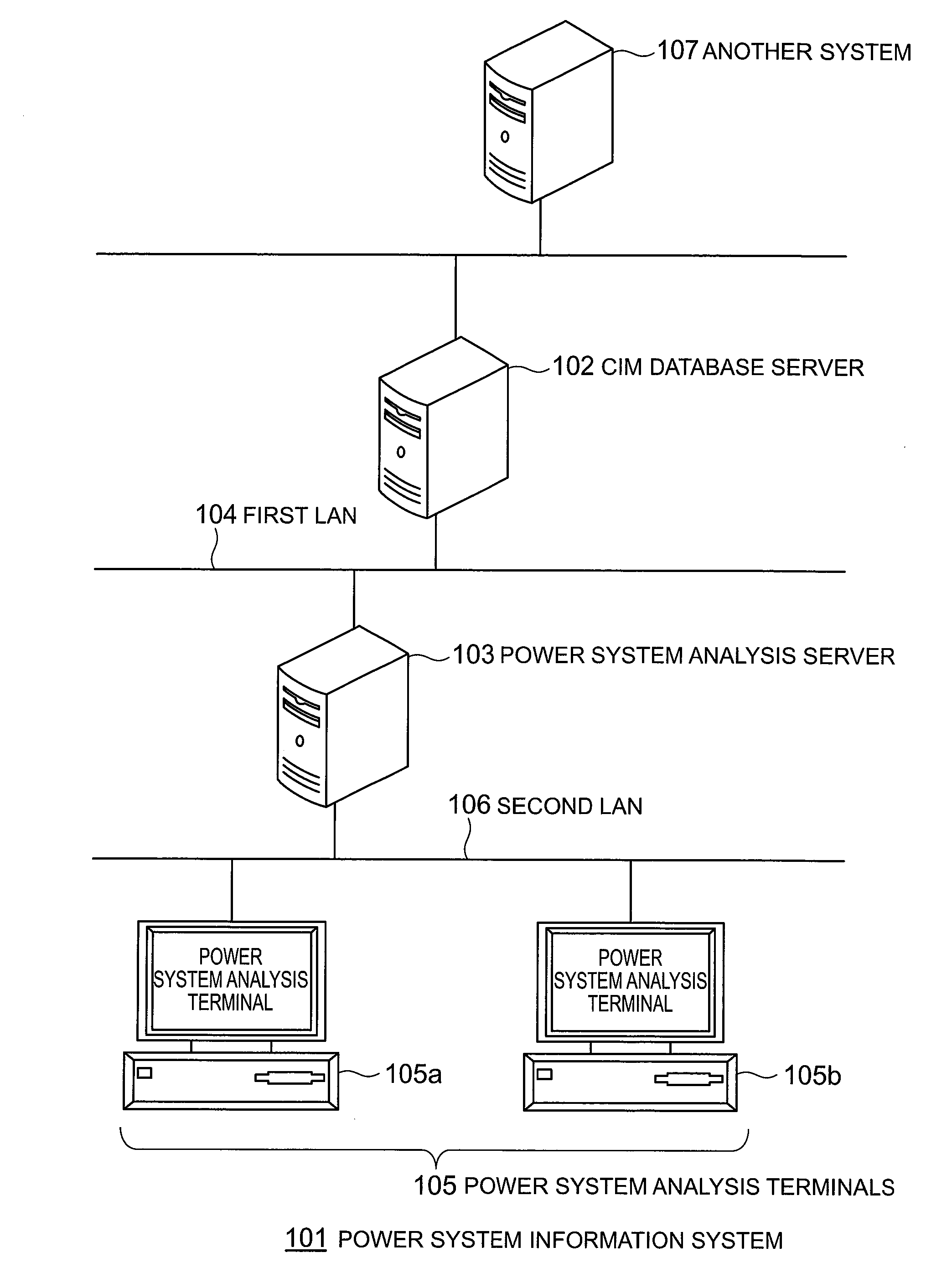
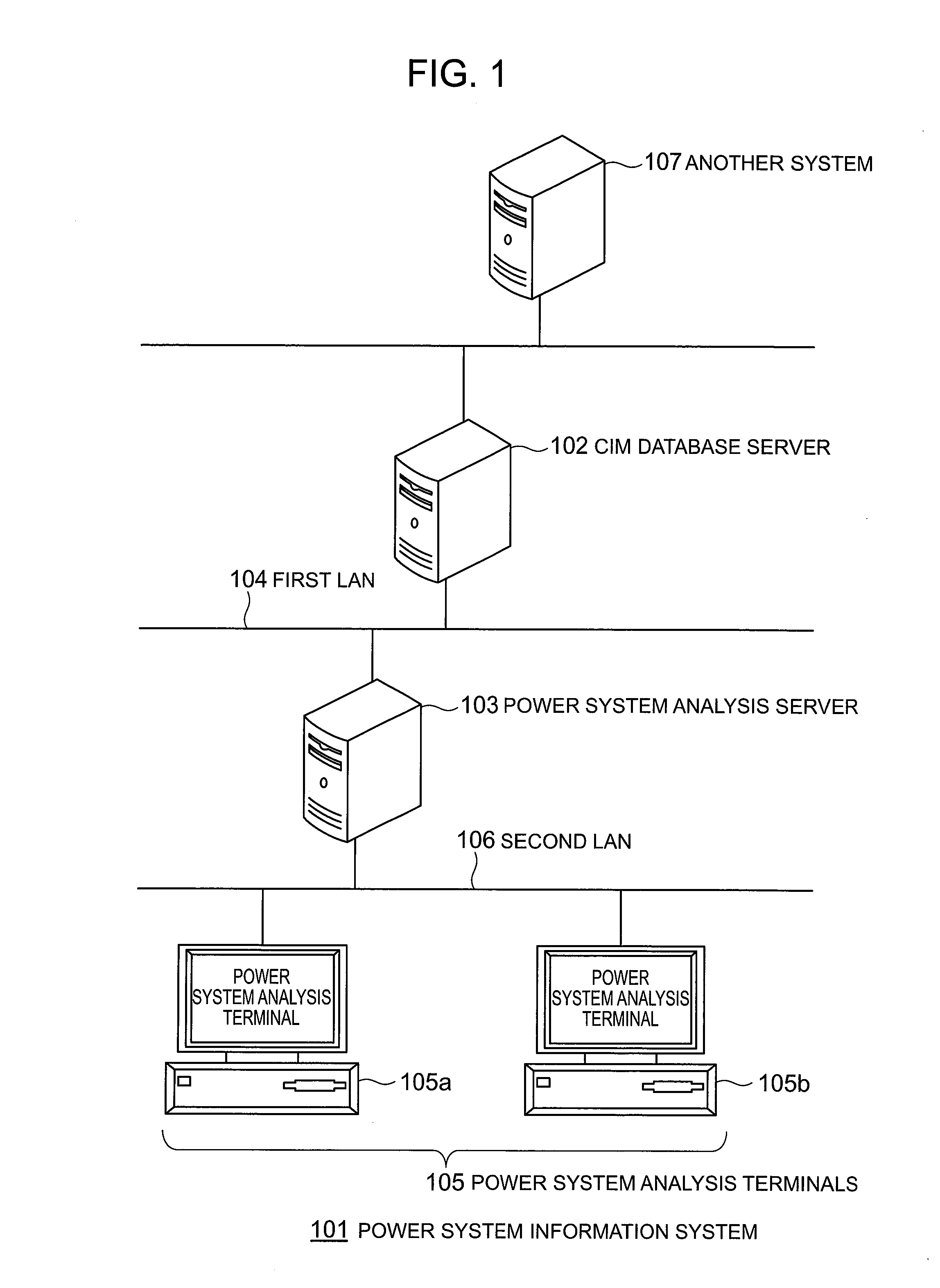
[0026]FIG. 1 is a block diagram schematically showing a power system information system 101 according to an embodiment of the present invention.

[0027]The power system information system 101 is configured by having a CIM database server 102 and a power system analysis server 103 each connected to a first LAN 104, and the power system analysis server 103 and a power system analysis terminal 105 each connected to a second LAN 106.

[0028]The CIM database server 102 is a database server which stores power facility data described by the CIM. The CIM database server 102 records data (device data) related to devices, such as a transformer, a generator, a load, a power line, etc., which are used for the power system, according to the CIM format. In addition, the CIM database server 102 also records information such as a relation of mutual connection among the respective devices, a value of power flow in the power system, an on / off state of a switch device, a position state of...


PUM


Abstract

A power system data model conversion method, a power system data model conversion system and a power system data model conversion program which are to perform a fast power system analysis and used for a power system analysis capable of reducing inconsistency with another information system, wherein all instances used for the power system analysis are read out from a CIM database server which is commonly used on a power system information system, and a connected relation between instances is constructed while performing recursive retrieval. And, conversion processing of the data model is performed to integrate information necessary for the power system analysis and dispersed to extend over the plural classes of a CIM data model into one class.

Description

BACKGROUND OF THE INVENTION[0001]The present invention relates to a conversion method, conversion system and conversion program of power system data models for converting the data model which is used for a power system facility to an appropriate format.[0002]The power system facility must keep supplying stable power for meeting the changing demands for power by users. Therefore, the power system facility is constantly monitored and its operating condition is analyzed. In order for such monitoring and analysis, a variety of information systems have been developed by many manufacturers including the present applicant. Specifically, they are an EMS (Energy Management System), a power system analysis system, a facility operation system, a statistical recording system, etc.[0003]Each of such information systems had its own particular power facility database. Therefore, there were disadvantages that different types of information systems cannot commonly use a facility data model, a mainte...

Claims


Application Information

Patent Timeline
Patent Type & Authority Applications(United States)
IPC IPC(8): G06F17/50
CPCG06F17/5009G06F30/20G06F2119/06
Inventor TOBE, SUMITOSUGIZAKI, YOUICHI
Owner HITACHI LTD
Why Eureka
Try Eureka