
High resistivity silicon-on-insulator substrate and method of forming

a silicon-on-insulator substrate and high-resistance technology, applied in the direction of semiconductor devices, semiconductor/solid-state device details, electrical apparatus, etc., can solve the problems of nonlinearity in electrical characteristics, free carriers in the handle substrate are susceptible to movement, and conventional fabrication techniques for forming semiconductor devices fail to address these concerns. , to achieve the effect of high resistivity, high resistivity

Inactive Publication Date: 2014-05-08
GLOBALFOUNDRIES INC
View PDF3 Cites 57 Cited by
  • Summary
  • Abstract
  • Description
  • Claims
  • Application Information

AI Technical Summary

Benefits of technology

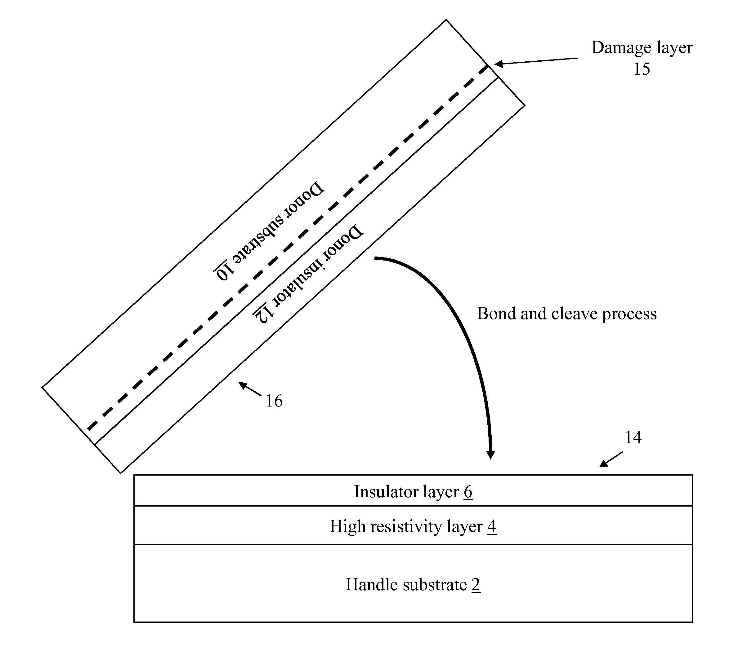
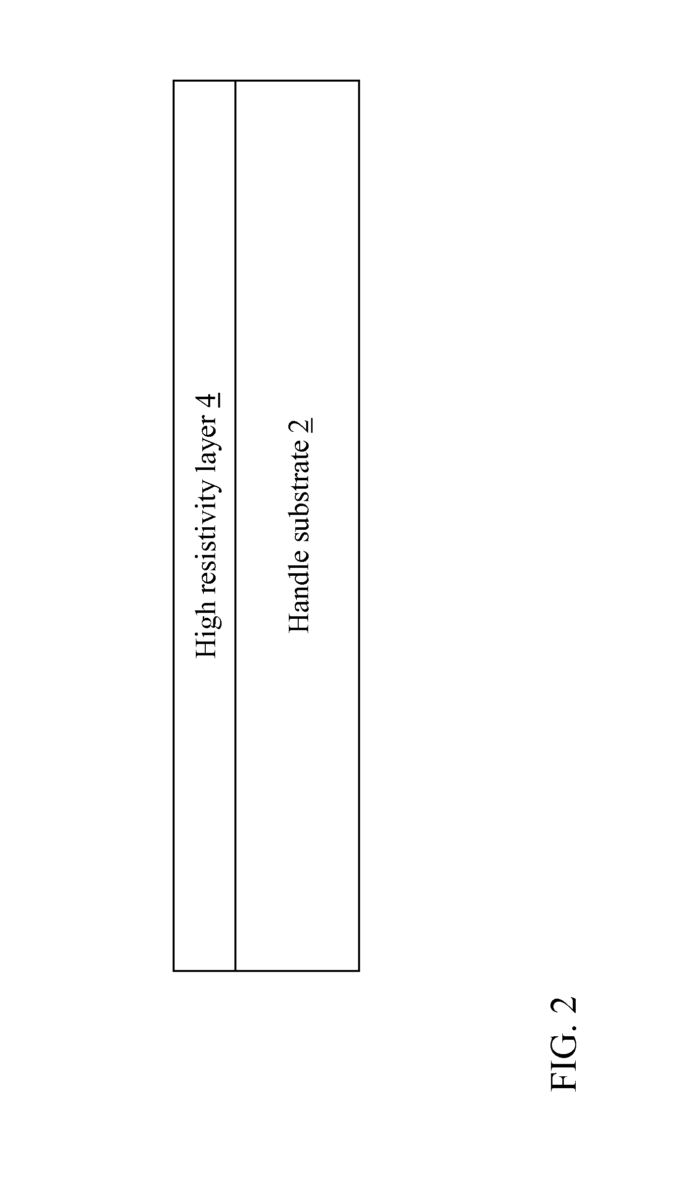
The patent text describes a method of making a silicon-on-insulator (SOI) wafer substrate. This involves creating a structure where a layer of silicon is placed on top of insulation material. This is done by depositing a layer of high resistivity material (such as silicon carbide or polycrystalline silicon) on a handle substrate, and then adding an insulator layer on top of the high resistivity material. The resulting substrate can then be used to create electronic components by bonding a donor wafer to the insulator layer. The technical effects of this method are improved insulation and reduced power leakage, which make it easier to create high-quality semiconductor devices.

Problems solved by technology

In these SOI RF devices, free carriers in the handle substrate are susceptible to movement caused by the electric fields created by potentials on the transistors and wires.
The movement of carriers is generally non-linear, and this non-linear “drag” both lowers the charge (Q) of passive components and creates nonlinearities in electrical characteristics.
Conventional fabrication techniques to form semiconductor devices fail to address these concerns.

Method used


Image

  • High resistivity silicon-on-insulator substrate and method of forming
  • High resistivity silicon-on-insulator substrate and method of forming
  • High resistivity silicon-on-insulator substrate and method of forming

Examples


Embodiment Construction

[0016]As noted herein, the subject matter disclosed relates to a silicon-on-insulator based integrated circuit structure. More specifically, the subject matter disclosed herein relates to an integrated circuit structure having a silicon-on-insulator substrate with a high resistivity.

[0017]In certain semiconductor devices, such as semiconductor-on-insulator (SOI) radio frequency (RF) devices, resistivity in the handle substrate can impact performance of the device. An example of such a device is a SOI RF complementary metal oxide semiconductor (CMOS) device. In these SOI RF devices, electric potentials on transistors and wires create electric fields, which in turn can cause movement of free carriers in the handle substrate. The movement of carriers is generally non-linear, and this non-linear “drag” both lowers the charge (Q) of passive components and creates nonlinearities in electrical characteristics. The handle substrate also acts as a path for heat removal from the active device...


PUM

PropertyMeasurementUnit
thickaaaaaaaaaa
thicknessaaaaaaaaaa
temperatureaaaaaaaaaa

Abstract

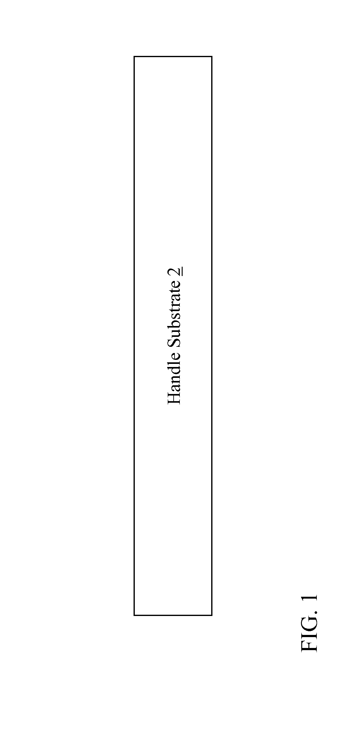
A semiconductor structure and a method of forming the same. In one embodiment, a method of forming a silicon-on-insulator (SOI) wafer substrate includes: providing a handle substrate; forming a high resistivity material layer over the handle substrate, the high resistivity material layer including one of an amorphous silicon carbide (SiC), a polycrystalline SiC, an amorphous diamond, or a polycrystalline diamond; forming an insulator layer over the high resistivity material layer; and bonding a donor wafer to a top surface of the insulator layer to form the SOI wafer substrate.

Description

CROSS-REFERENCE TO RELATED APPLICATION[0001]This application is a divisional application of co-pending U.S. patent application Ser. No. 13 / 342,697, filed Jan. 3, 2012, which is hereby incorporated herein in its entirety.FIELD[0002]The subject matter disclosed herein relates to a silicon-on-insulator based semiconductor structure. More specifically, the subject matter disclosed herein relates to a semiconductor structure having a silicon-on-insulator substrate with a high resistivity.BACKGROUND[0003]In certain semiconductor devices, such as semiconductor-on-insulator (SOI) radio frequency (RF) devices, resistivity in the handle substrate can impact performance of the device. An example of such a device is a SOI RF complementary metal oxide semiconductor (CMOS) device. In these SOI RF devices, free carriers in the handle substrate are susceptible to movement caused by the electric fields created by potentials on the transistors and wires. The movement of carriers is generally non-line...

Claims


Application Information

Patent Timeline
Patent Type & Authority Applications(United States)
IPC IPC(8): H01L29/16
CPCH01L29/16H01L21/76254H01L21/02002
Inventor BOTULA, ALAN B.JAFFE, MARK D.JOSEPH, ALVIN J.
Owner GLOBALFOUNDRIES INC
Learn More