Poly-Phase Reluctance Electric Motor with Transverse Magnetic Flux

Active Publication Date: 2014-05-08
HARBIN INST OF TECH
View PDF1 Cites 6 Cited by
  • Summary
  • Abstract
  • Description
  • Claims
  • Application Information

AI Technical Summary

Benefits of technology

The present invention is a multi-phase reluctance electric motor with transverse magnetic flux that employs a unique armature structure to improve control precision, reduce copper loss, and increase efficiency. It is easy to modulate torque and achieve field of applicability targets. The permanent magnets are positioned on the stator to improve reliability and safety. The small amount of armature coil needed and simple processing procedure make it cost-effective. Overall, the electric motor is simple in design, easy to improve, and highly efficient.

Problems solved by technology

A conventional multi-phase permanent magnet synchronous motor is disclosed in FIG. 1 of the drawings of which the armature winding is a distributed winding which requires a large number of coils to build the winding, the end wires of each winding intersect with each other, the end wires are long and the copper loss is great, and the insulation of the winding is complex and the manufacturing cost is high.
Because there exists magnetic coupling between separate phases, the mutual inductance will adversely affect the precision on current control.
On the other hand, the magnetic flux generated by the winding in each phase will pass through a relative long flux path, therefore the stator iron loss is relatively great and further increase of motor efficiency is restricted.
Also, the permanent magnet is positioned on the stator and the structural strength and allowable temperature rise of the stator are restricted, hence the application of electric motor is limited.

Method used


Image

  • Poly-Phase Reluctance Electric Motor with Transverse Magnetic Flux
  • Poly-Phase Reluctance Electric Motor with Transverse Magnetic Flux
  • Poly-Phase Reluctance Electric Motor with Transverse Magnetic Flux

Examples


embodiment 1

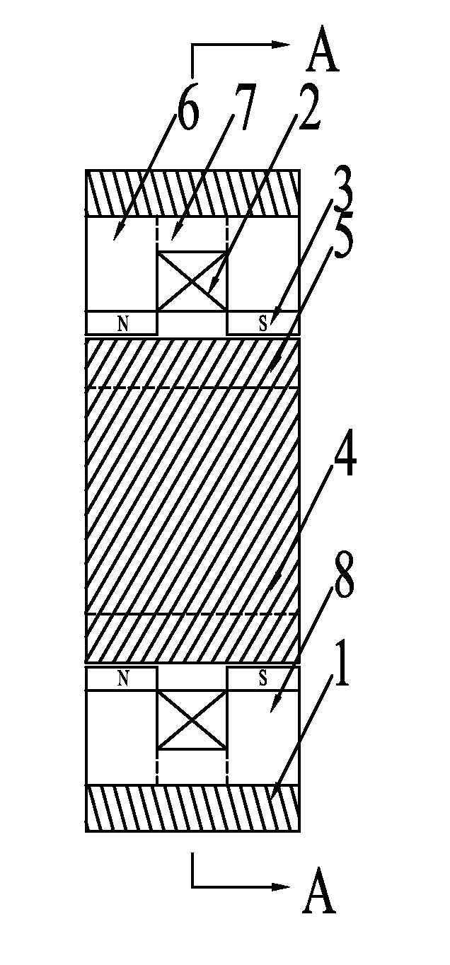
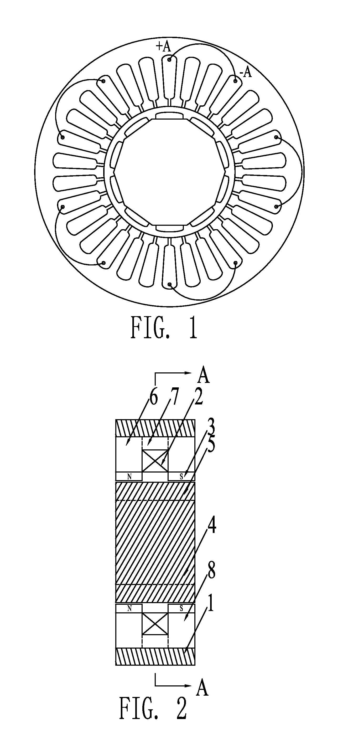
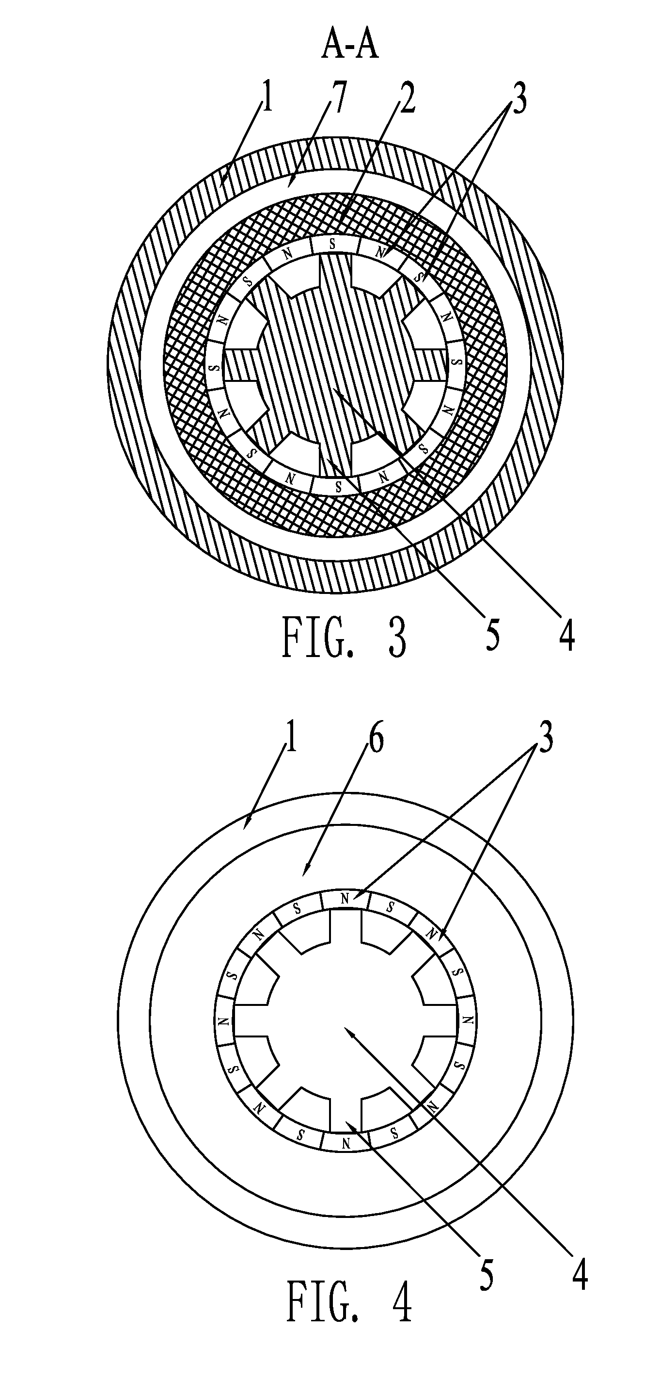
[0043] The multi-phase reluctance electric motor with transverse magnetic flux according to this preferred embodiment of the present invention is illustrated in FIG. 2, FIG. 3 and FIG. 4 of the drawings. The multi-phase reluctance electric motor with transverse magnetic flux according to this preferred embodiment of the present invention comprises a stator and a rotor; wherein a gas partition channel is defined between the stator and the rotor; wherein the rotor comprises a rotor frame unit 4 and a plurality of rotor teeth 5; wherein the plurality of rotor teeth 5 are uniformly distributed along the outer circumferential portion of the rotor frame unit 4; wherein the rotor frame unit 4 and the rotor teeth 5 have an integrated structure; wherein the stator comprises a housing 1 and an armature unit with m number of phases defining m number of single-phase armature members, where m is the number of phases of the electric motor and m is equal to or greater than 3; wherein the housing 1...

embodiment 2

[0044] The multi-phase reluctance electric motor with transverse magnetic flux according to this preferred embodiment of the present invention is illustrated in FIG. 5, FIG. 6 and FIG. 7 of the drawings. The multi-phase reluctance electric motor with transverse magnetic flux according to this preferred embodiment of the present invention comprises a stator and a rotor; wherein a gas partition channel is defined between the stator and the rotor; wherein the rotor comprises a rotor frame unit 4 and a plurality of rotor teeth 5; wherein the plurality of rotor teeth 5 are uniformly distributed along the outer circumferential portion of the rotor frame unit 4; wherein the rotor frame unit 4 and the rotor teeth 5 have an integrated structure; wherein the stator comprises a housing 1 and an armature unit with m number of phases defining m number of single-phase armature members, where m is the number of phases of the electric motor and m is equal to or greater than 3; wherein the housing 1...

embodiment 3

[0045] The multi-phase reluctance electric motor with transverse magnetic flux according to this preferred embodiment of the present invention is illustrated in FIG. 8, FIG. 9 and FIG. 10 of the drawings. The multi-phase reluctance electric motor with transverse magnetic flux according to this preferred embodiment of the present invention comprises a stator and a rotor; wherein a gas partition channel is defined between the stator and the rotor; wherein the rotor comprises a rotor frame unit 4 and a plurality of rotor teeth 5; wherein the plurality of rotor teeth 5 are uniformly distributed along the outer circumferential portion of the rotor frame unit 4; wherein the rotor frame unit 4 and the rotor teeth 5 have an integrated structure; wherein the stator comprises a housing 1 and an armature unit with m number of phases defining m number of single-phase armature members, where m is the number of phases of the electric motor and m is equal to or greater than 3; wherein the housing ...


PUM


Abstract

Disclosed is a poly-phase reluctance electric motor with transverse magnetic flux, which electric motor is composed of a stator and a rotor. The stator is composed of a housing (1) and a number m of phase armature units which are arranged within the housing (1) along the axial direction successively, with each of the phase armature units being staggered at an electrical angle of 360° / m along the circumferential direction. Each phase armature unit is composed of a unit armature iron core, an armature coil (2) and permanent magnets (3), with the unit armature iron core being composed of a first annular iron core segment (6), a second annular iron core segment (7) and a third annular iron core segment (8). The armature coil (2) is embedded within an annular space formed among the first to the third annular iron core segments (6, 7, 8). The permanent magnets (3) are fixedly arranged on the inner surfaces of the first and the third annular iron core segments (6, 8) along the circumferential direction in a manner of the N pole and the S pole spaced successively. The pole distance τm between every two adjacent permanent magnets (3) on the same annular iron core segment and the tooth distance τp between the rotor teeth (5) arranged along the circumferential direction fulfil 2τm=τp. The electric motor eliminates the mutual inductance between phases, improving the precision with which the current and electromagnetic torque of the electric motor can be controlled and the dynamic characteristics of the system, and improving the reliability and safety of the motor as a result of the permanent magnets (3) being located on the stator.

Description

BACKGROUND OF THE PRESENT INVENTION[0001]1. Field of Invention[0002]The present invention relates to a reluctance motor, and more particularly to a poly-phase reluctance motor.[0003]2. Description of Related Arts[0004]A conventional multi-phase permanent magnet synchronous motor is disclosed in FIG. 1 of the drawings of which the armature winding is a distributed winding which requires a large number of coils to build the winding, the end wires of each winding intersect with each other, the end wires are long and the copper loss is great, and the insulation of the winding is complex and the manufacturing cost is high. Because there exists magnetic coupling between separate phases, the mutual inductance will adversely affect the precision on current control. On the other hand, the magnetic flux generated by the winding in each phase will pass through a relative long flux path, therefore the stator iron loss is relatively great and further increase of motor efficiency is restricted. A...

Claims


Application Information

Patent Timeline
IPC IPC(8): H02K1/17
CPCH02K1/17H02K21/44H02K2201/12
Inventor KOU, BAOQUANXIE, DAGANGWU, TAIJIANZHOU, YIHENG
Owner HARBIN INST OF TECH
Why Eureka
Try Eureka