Antenna device
- Summary
- Abstract
- Description
- Claims
- Application Information
AI Technical Summary
Benefits of technology
Problems solved by technology
Method used
Image
Examples
first embodiment
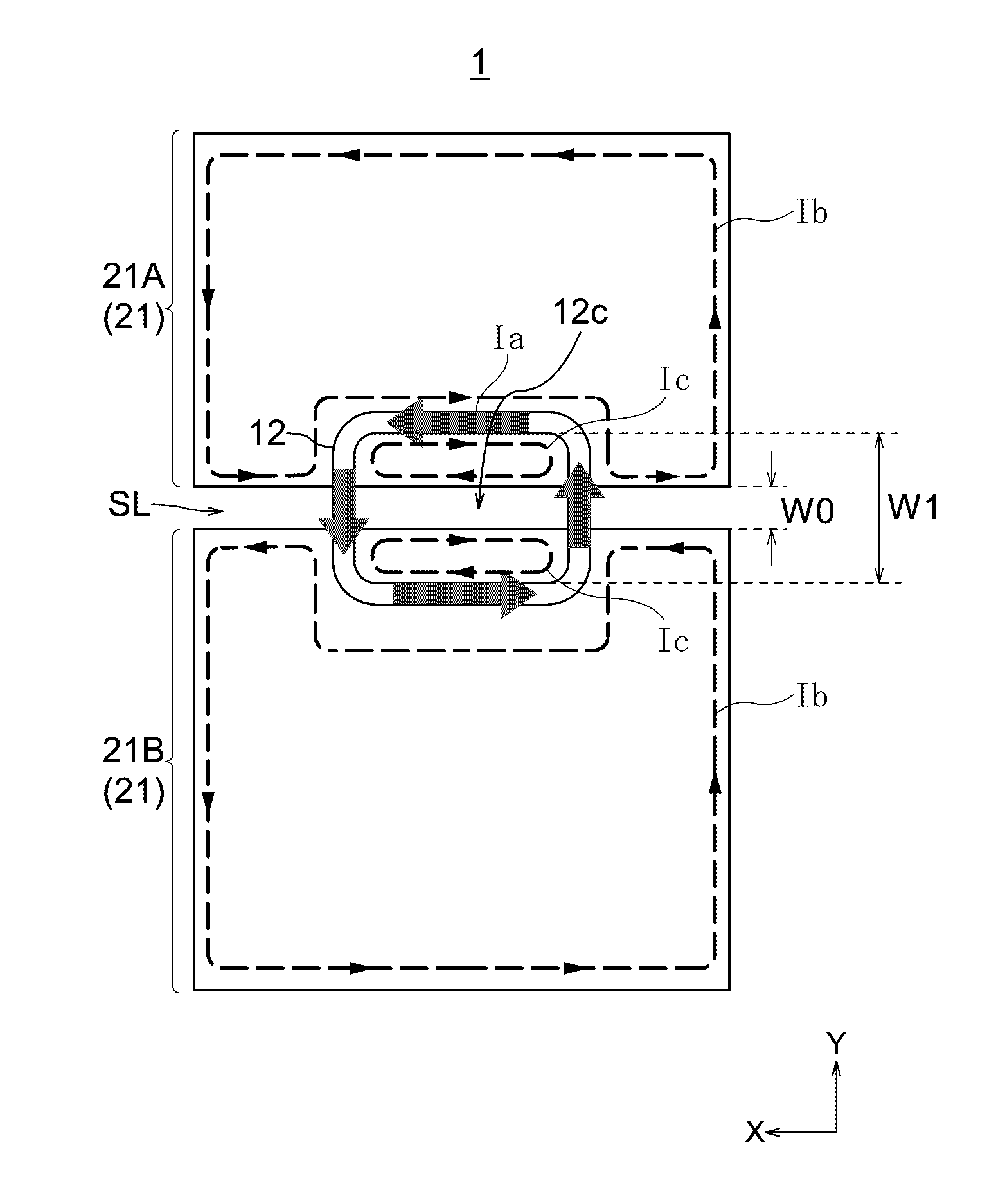
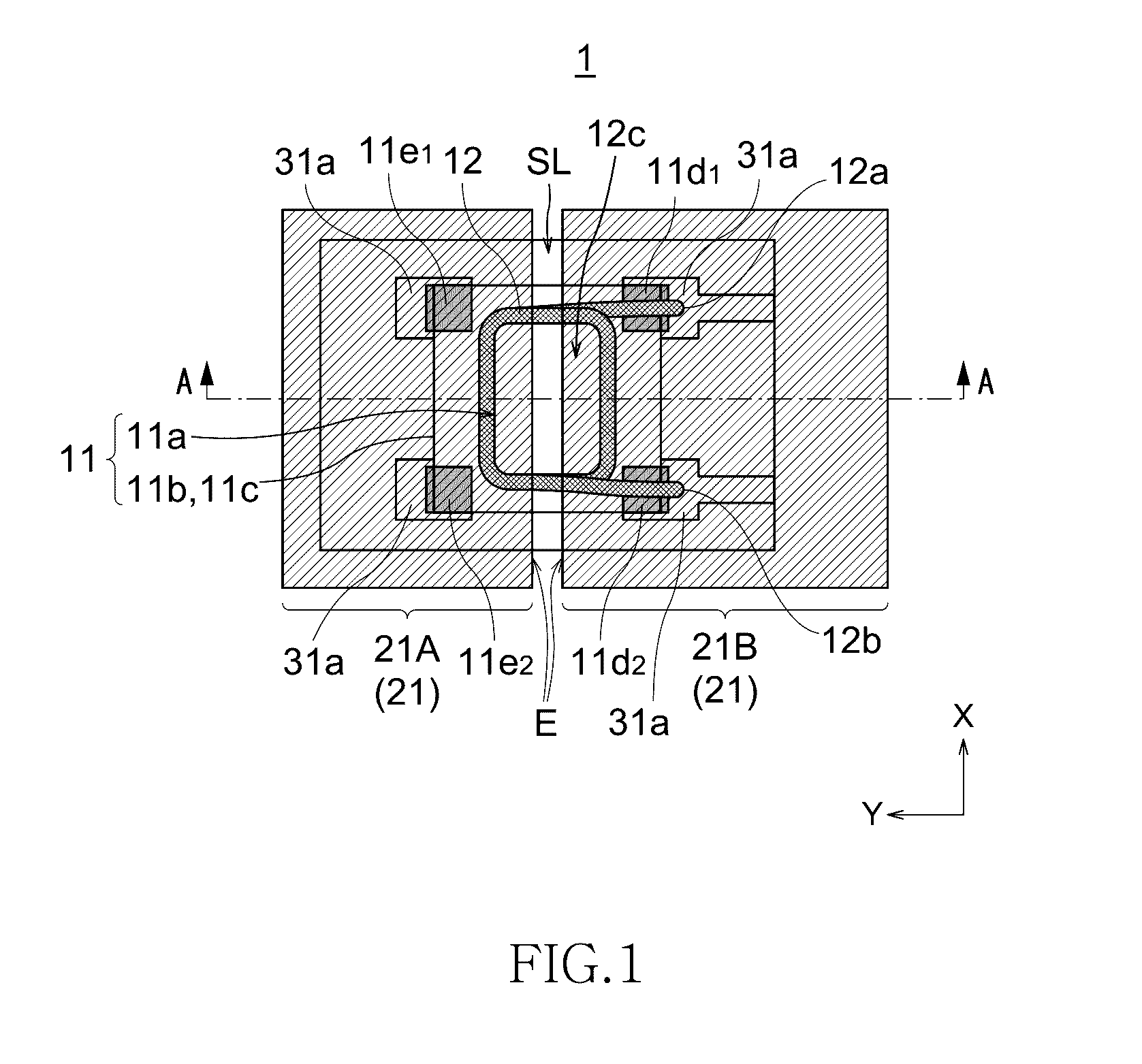
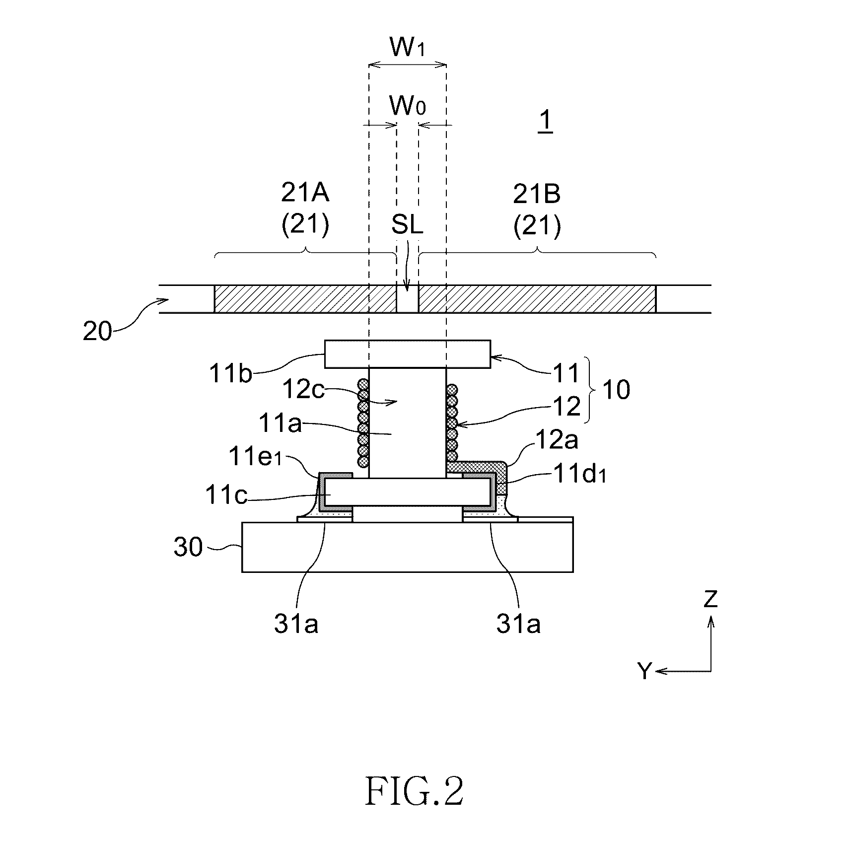
[0028]FIG. 1 is a schematic plan view transparently illustrating a configuration of an antenna device according to the present invention, and FIG. 2 is a schematic cross-sectional side view of the antenna device taken along a line A-A of FIG. 1.
[0029]As illustrated in FIGS. 1 and 2, an antenna device 1 has a wound-type antenna coil 12 wound around a drum-shaped magnetic core 11 and a metal layer 21 covering from above the antenna coil 12. The magnetic core 11 and the antenna coil 12 constitute a surface-mountable wound-type coil component 10. The metal layer 21 constitutes the entire or a part of a casing 20 of a mobile electronic device and is disposed perpendicular to a coil axis (Z-axis) of the antenna coil 12 in a plan view. It is assumed that the metal layer 21 side is positioned above the antenna coil 12, and a side opposite to the metal layer 21 is positioned below the antenna coil 12.
[0030]The magnetic core 11 has a winding core 11a and a pair of flanges 11b and 11c provided...
second embodiment
[0042]FIG. 5 is a schematic cross-sectional view illustrating a configuration of an antenna device according to the present invention.
[0043]As illustrated in FIG. 5, an antenna device 2 of the present embodiment is featured in that the first flange 11b is smaller in size than the second flange 11c. More specifically, an area of an outer side surface Sb of the first flange 11b is smaller than an area of an outer side surface Sc of the second flange 11c. To realize such a configuration, in the present embodiment, a width W2 of the first flange 11b in the Y-direction perpendicular to the extending direction (X-direction) of the slit SL is made smaller than a width W3 of the second flange 11c in the Y-direction. Alternatively, however, a width of the first flange lib in the X-direction may be made smaller than a width of the second flange 11c in the X-direction. Further alternatively, the widths of the first flange 11b in the X- and Y-directions maybe made smaller than the widths of the...
third embodiment
[0046]FIG. 6 is a schematic cross-sectional view illustrating a configuration of an antenna device according to the present invention.
[0047]As illustrated in FIG. 6, an antenna device 3 of the present embodiment is featured in that a magnetic sheet 32 larger in size than the second flange 11c is provided at the outer side surface Sb (lower surface) side of the second flange 11c. A width W5 of the magnetic sheet 32 in the Y-direction is larger than a width W4 of the second flange 11c in the Y-direction. A width of the magnetic sheet 32 in the X-direction may be made larger than a width of the second flange 11c in the X-direction.
[0048]Further, in the present embodiment, the second flange 11c of the magnetic core 11 is fixedly bonded to an upper surface of the printed circuit board 30 through the magnetic sheet 32. Further, the one end 12a and the other end 12b of the antenna coil 12 are connected respectively to the pair of signal terminals 11d1 and 11d2 provided on the second flange...
PUM
 Abstract
Description
Claims
Application Information
 - R&D
- Intellectual Property
- Life Sciences
- Materials
- Tech Scout
- Unparalleled Data Quality
- Higher Quality Content
- 60% Fewer Hallucinations
Browse by: Latest US Patents, China's latest patents, Technical Efficacy Thesaurus, Application Domain, Technology Topic, Popular Technical Reports.
© 2025 PatSnap. All rights reserved.Legal|Privacy policy|Modern Slavery Act Transparency Statement|Sitemap|About US| Contact US: help@patsnap.com


