

Energy receiver, detection method, power transmission system, detection device, and energy transmitter
a technology of energy receiver and detection method, which is applied in the direction of charging stations, instruments, transportation and packaging, etc., can solve the problems of not considering the influence of metal housing on the power reception side, difficult to determine whether the parameter change difficult to determine whether the eddy current loss is caused by a metal housing in a mobile device, etc., to achieve the effect of improving detection accuracy
Active Publication Date: 2014-05-08
SONY CORP
View PDF8 Cites 46 Cited by
- Summary
- Abstract
- Description
- Claims
- Application Information
AI Technical Summary
Benefits of technology
The patent aims to detect foreign metals between the power transmission and reception sides to improve detection accuracy without adding burden to the power reception side. This is achieved by measuring the secondary-side quality factor while power feeding is not performed from the power transmission side to the power reception side. The patent provides a method to detect foreign metals without being affected by power feeding, resulting in improved detection accuracy.
Problems solved by technology
However, in the methods proposed in Patent Literatures 1 and 2, influence of a metal housing on the power reception side is not considered.
In the case of charging to general mobile devices, any metal (metal housings, metallic parts, and the like) is likely to be used in the mobile devices, and thus it is difficult to determine whether the change of the parameters is caused by “influence of the metal housing and the like” or by “a contained foreign metal”.
In Patent Literature 2 as an example, it is difficult to determine whether the eddy current loss is caused by a metal housing in a mobile device or by a foreign metal existing between a power transmission side and a power reception side.
However, when a detection circuit detecting a foreign metal is operated by using power charged in the battery in the mobile device, the mobile device is necessary to control the detection circuit while appropriately controlling the battery, and thus load related to the control is large.
Moreover, when the remaining battery charge is little, it is difficult for the mobile device to detect a foreign metal existing between the mobile device and the power transmission side.
If detection of a foreign metal is not performed, power transmission from the power transmission side is not performed because safety is not ensured, and thus the battery is not charged.
Method used
View moreImage
Smart ImageViewing Examples

Examples
first embodiment (
1. First Embodiment (first to third switch sections: example of switching circuit between during power feeding and during quality factor measurement)
second embodiment (
2. Second Embodiment (arithmetic processing section: example of calculating quality factor by half bandwidth method)
third embodiment (
3. Third Embodiment (arithmetic processing section: example of calculating quality factor with use of ratio of real component and imaginary component of impedance)
4. Others (various modifications)
Login to View More PUM
 Abstract
An energy receiver includes: a power receiver coil configured to wirelessly receive power transmitted from a power transmitter; a detection section configured to detect a foreign object; and a power storage section configured to supply power to the detection section during detection of the foreign object.
Description
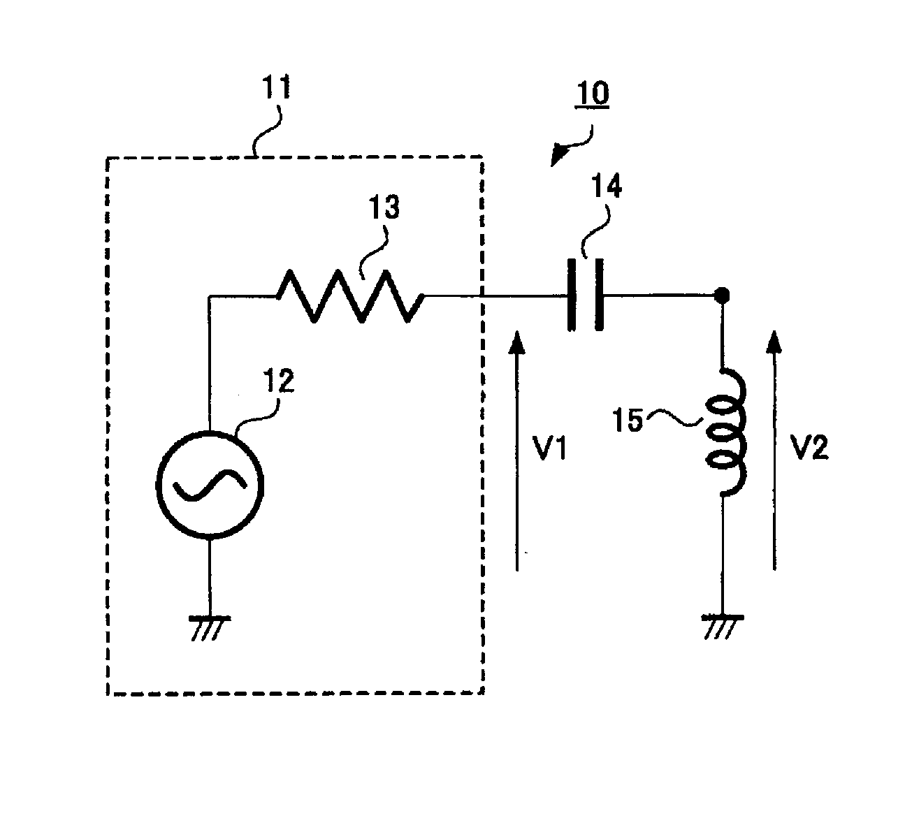
TECHNICAL FIELD[0001]The present disclosure relates to a detector detecting presence of a conductor such as a metal, a power receiver, a power transmitter, a non-contact power transmission system, and a detection method. In particular, the present disclosure relates to an energy receiver, a detection method, a power transmission system, a detection device, and an energy transmitter.BACKGROUND ART[0002]In recent years, a non-contact power transmission system supplying power by wireless, that is, without contact is actively developed. A magnetic field resonance method attracts attention as a method realizing non-contact power transmission. The magnetic field resonance method uses magnetic field coupling between a transmission-side coil and a reception-side coil to perform power transmission. The magnetic field resonance method has characteristics that magnetic fluxes shared between a power feed source and a power feed destination is reduced by actively using resonance phenomenon.[0003...
Claims
Login to View More Application Information
Patent Timeline
 IPC IPC(8): H01F38/14H02J7/02
CPCH02J7/025H01F38/14H02J5/005G01V3/101H02J7/00034Y02T10/70Y02T10/7072Y02T90/14H02J50/12H02J50/60H02J7/0068H02J50/80H02J50/90B60L53/122B60L53/124H02J50/10B60L53/12
InventorNAKANO, HIROAKIFUKUDA, SHINICHIMURAYAMA, YUJIFUJIMAKI, KENICHIMURAKAMI, TOMOMICHI
OwnerSONY CORP