Hot stick power analyzer

a power analyzer and hot stick technology, applied in the direction of measuring devices, resistance/reactance/impedence, instruments, etc., can solve the problems of no physical ground connection and require high-precision calibration

Active Publication Date: 2014-05-08
FOSTER-MILLER
View PDF4 Cites 13 Cited by
  • Summary
  • Abstract
  • Description
  • Claims
  • Application Information

AI Technical Summary

Problems solved by technology

These sensors have no physical ground connection and require highly accurate calibration of voltage and phase angle in their installation environment.

Method used


Image

  • Hot stick power analyzer
  • Hot stick power analyzer
  • Hot stick power analyzer

Examples


Embodiment Construction

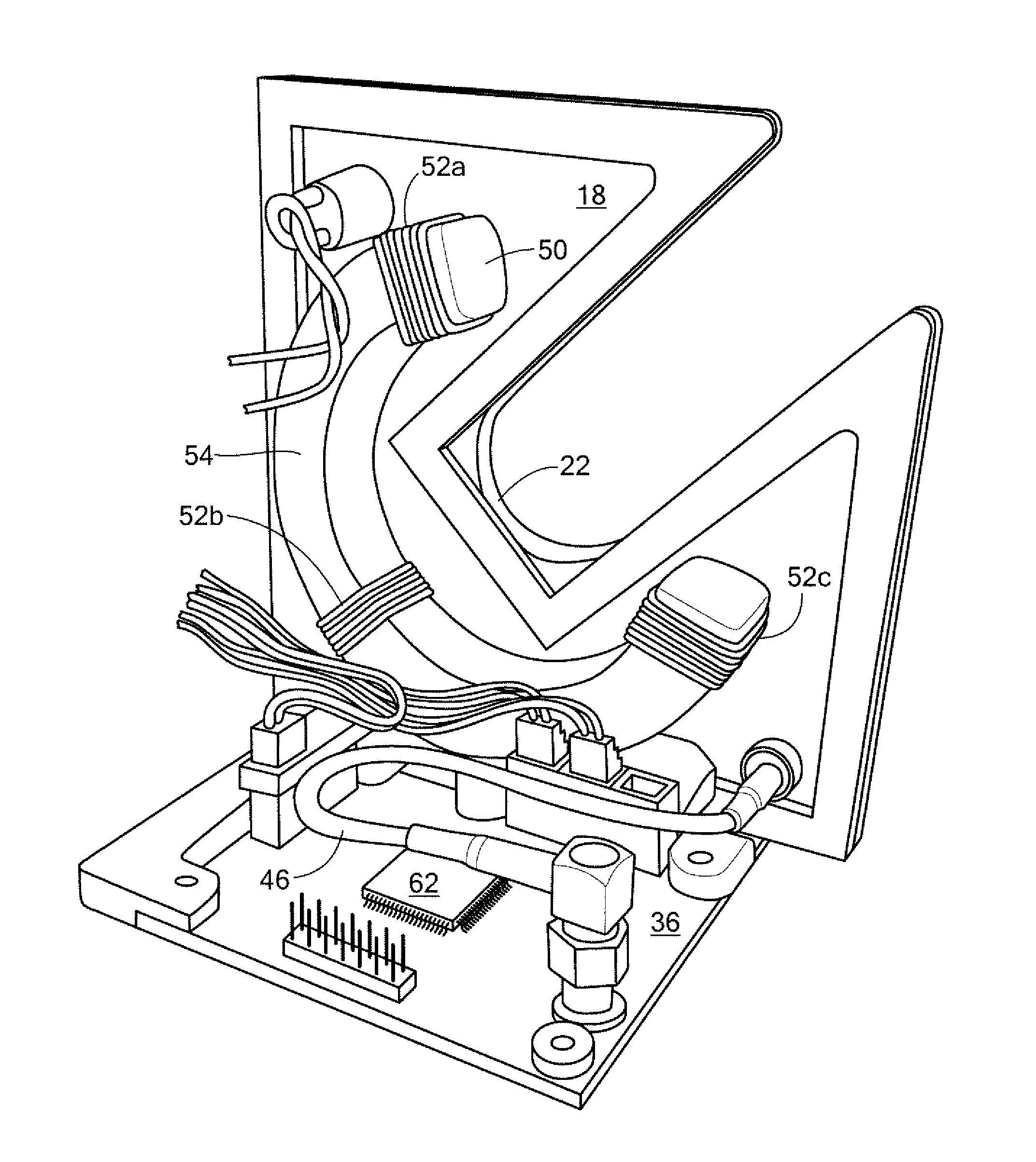
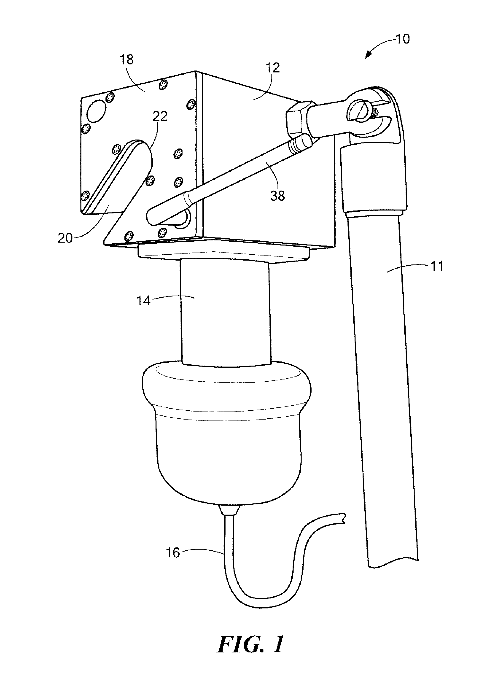
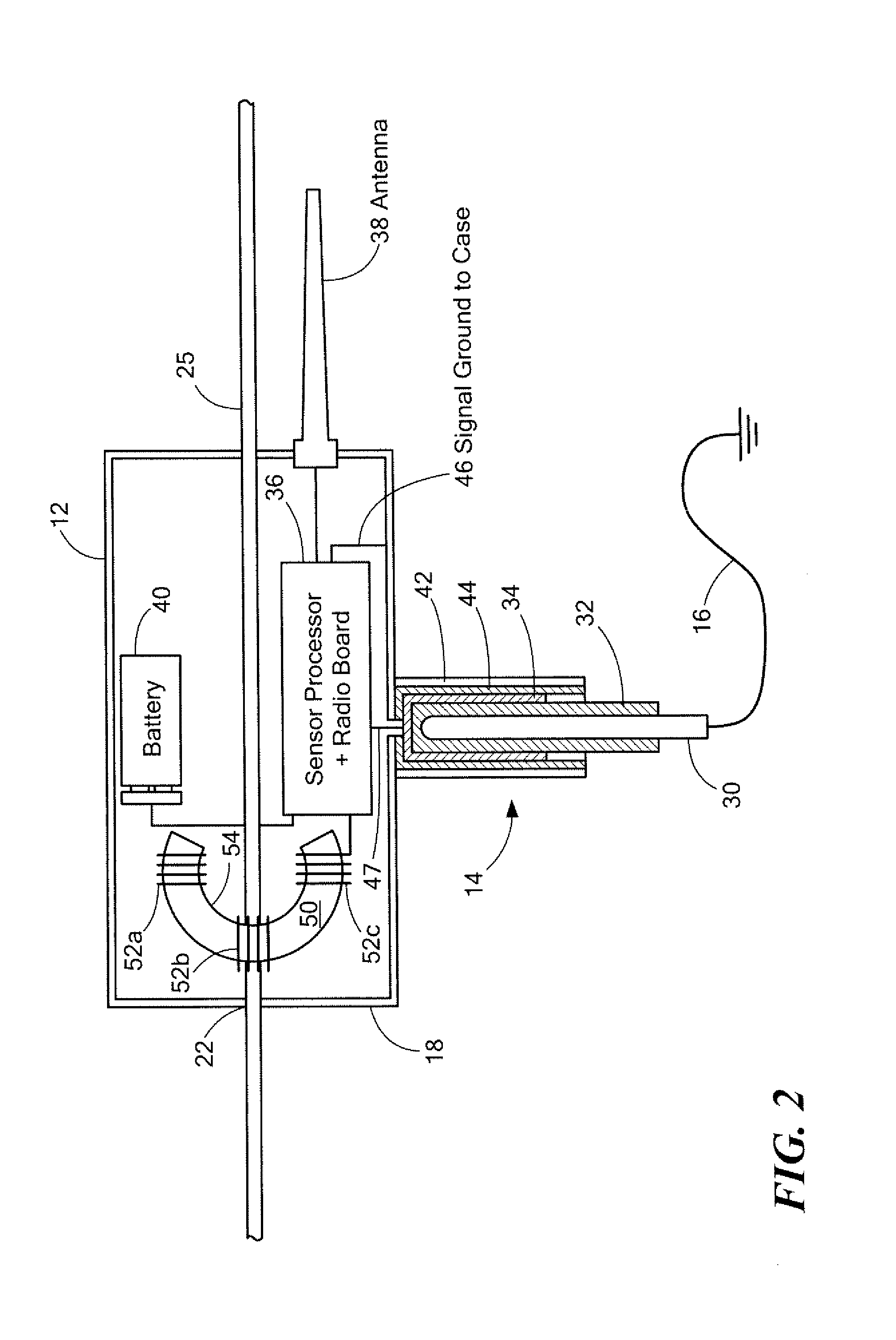
[0032]The hot stick-mounted sensor device is typically a small housing mounted on the end of a “hot stick” pole. A high voltage capacitor is used to sense the voltage on the distribution line. One end of the capacitor is connected to the input of a voltage sensing circuit. A cable on the other end of the capacitor makes a connection to ground. An air-cored coil, also known as a “Rogowski coil”, senses the current flowing in the distribution line. The coil creates a voltage proportional to the time derivative of current in the line without loading the line in a significant way.

[0033]A low-power microcontroller can be used to rapidly (˜8000 times per second) sample the voltage and current test circuits and compute associated quantities like RMS voltage, RMS current, real power, and reactive power.

[0034]A wireless transceiver transmits measurements via radio to a modem attached to a laptop. Because the microcontroller is at high voltage, it can be dangerous to have a direct cable conne...


PUM


Abstract

A hot stick power analyzer includes a housing mounted on a pole and a channel for a power line. A ground line extends from the housing and there is a power line conductive contact. A voltage sensor includes voltage sensing circuitry connected to the power line conductive contact and the ground line. There is a high voltage capacitance between the ground line and the voltage sensing circuitry. A current sensor includes windings about and spaced from the power line. A processing subsystem is responsive to the voltage sensing circuitry and to the current sensor and is configured to compute power analysis metrics.

Description

RELATED APPLICATIONS[0001]This application claims benefit of and priority to U.S. Provisional Application Ser. No. 61 / 722,417 filed Nov. 5, 2012 under 35 U.S.C. §§119, 120, 363, 365, and 37 C.F.R. §1.55 and §1.78 and is incorporated herein by this reference.FIELD OF THE INVENTION[0002]The invention relates to power line voltage and current measurement devices.BACKGROUND OF THE INVENTION[0003]Presently, three types of hot stick electrical measurement equipment are available for performing spot measurements. A hot stick voltmeter measures the voltage between a medium voltage (MV) line and ground, typically using a resistive voltage divider. A typical example is the instrument described at http: / / www.rossengineeringcorp.com / hi-z_hv_voltmeters.htm incorporated herein by this reference. The device connects to the line and has a connection to ground.[0004]A hot stick ammeter measures the current flowing in a MV line, typically using an air-cored coil as the sensor. A typical example is th...

Claims


Application Information

Patent Timeline
Patent Type & Authority Applications(United States)
IPC IPC(8): G01R21/06G01R35/00
CPCG01R35/005G01R21/06G01R15/142G01R19/2513G01R15/16
Inventor MASON, TIMOTHY J.MEEKER, DAVID C.GODFREY, JAMES F.TRAVIS, JEFFREY C.LEARY, WILLIAM G.POST, ALEXANDER E.
Owner FOSTER-MILLER
Why Eureka
Try Eureka