Touch device with photovolatic conversion function

Inactive Publication Date: 2014-05-08
CHIH CHUNG LIN
View PDF11 Cites 1 Cited by
  • Summary
  • Abstract
  • Description
  • Claims
  • Application Information

AI Technical Summary

Benefits of technology

[0006]By combining the photovoltaic conversion layer with the main body of the touch device, more light can be absorbed and converted into electric energy by the photovoltaic conversion layer for storing in the touch device, so that the touch device can have extended standby and operation time.
[0007]Further, by

Problems solved by technology

As a result, the portable electronic device would

Method used


Image

  • Touch device with photovolatic conversion function
  • Touch device with photovolatic conversion function
  • Touch device with photovolatic conversion function

Examples


first embodiment

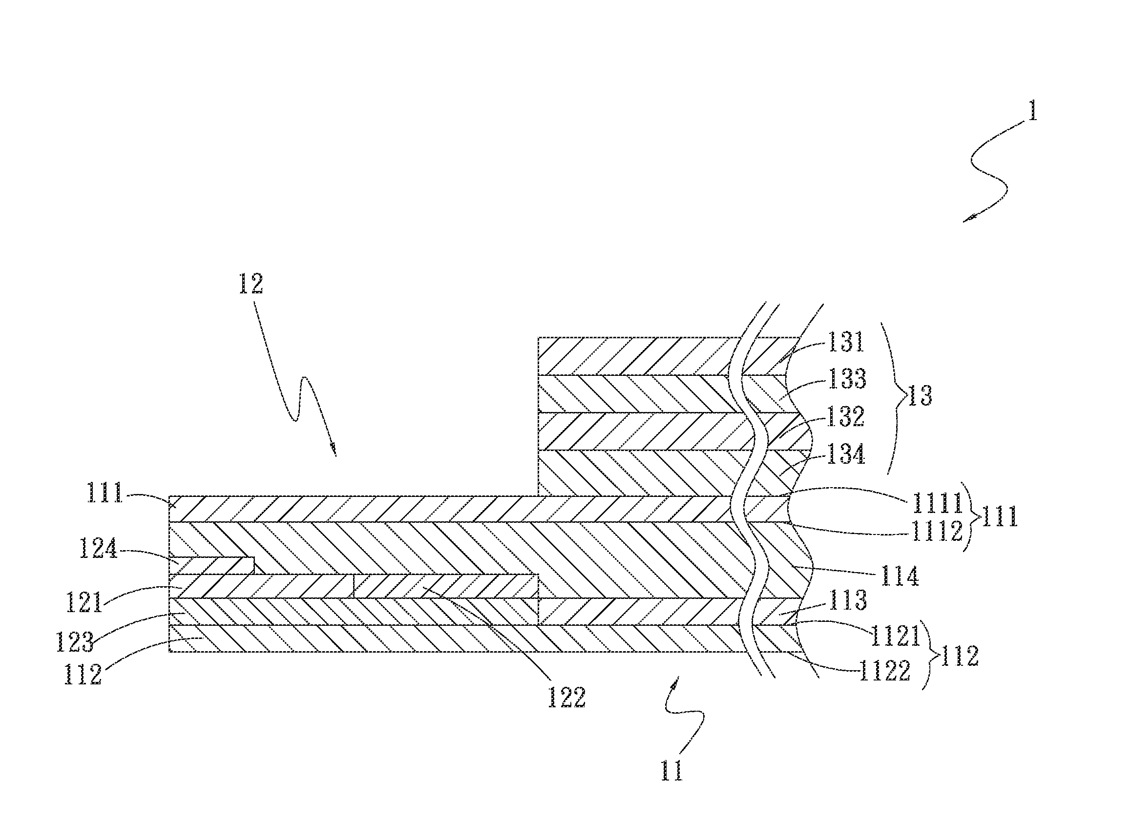
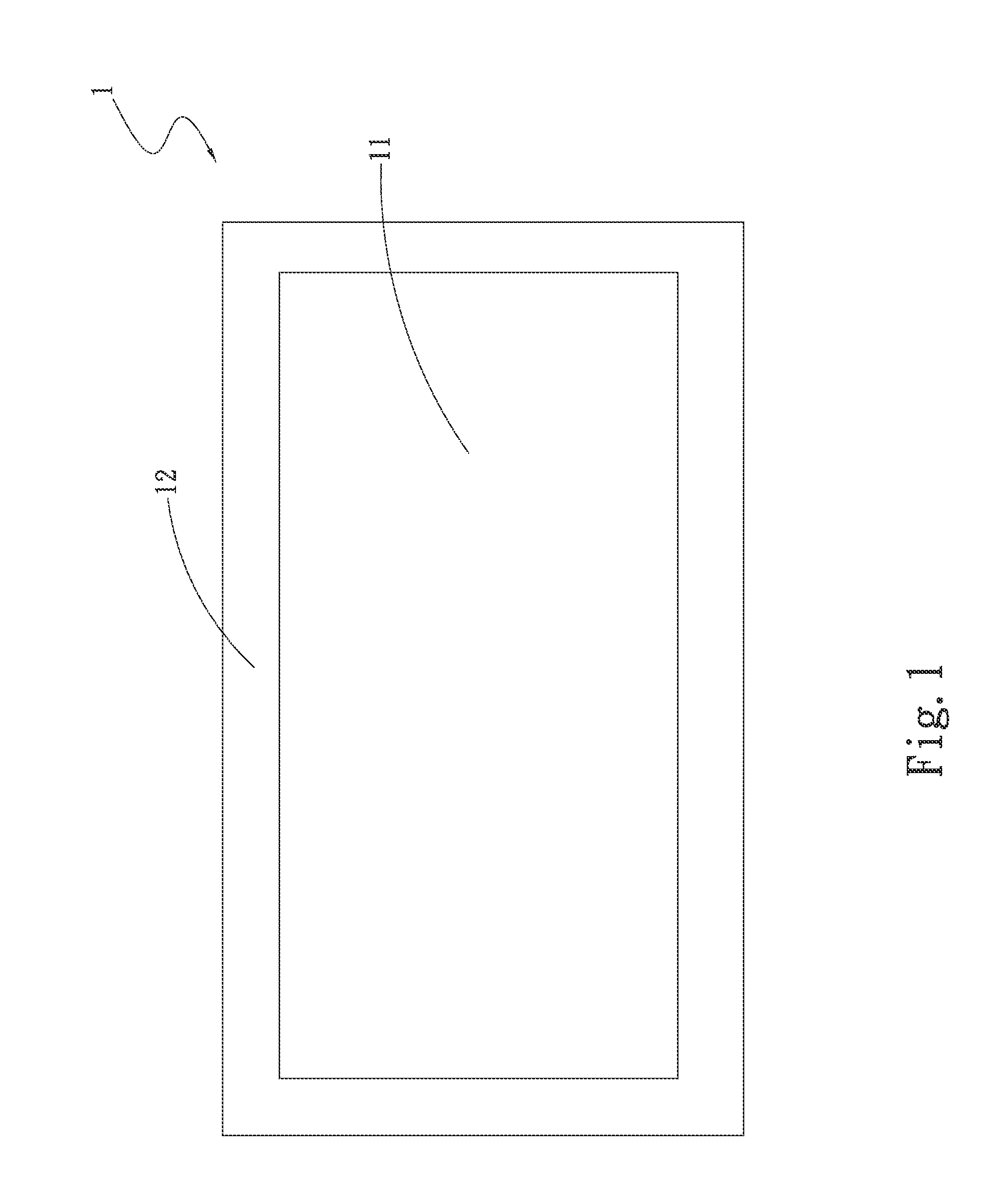
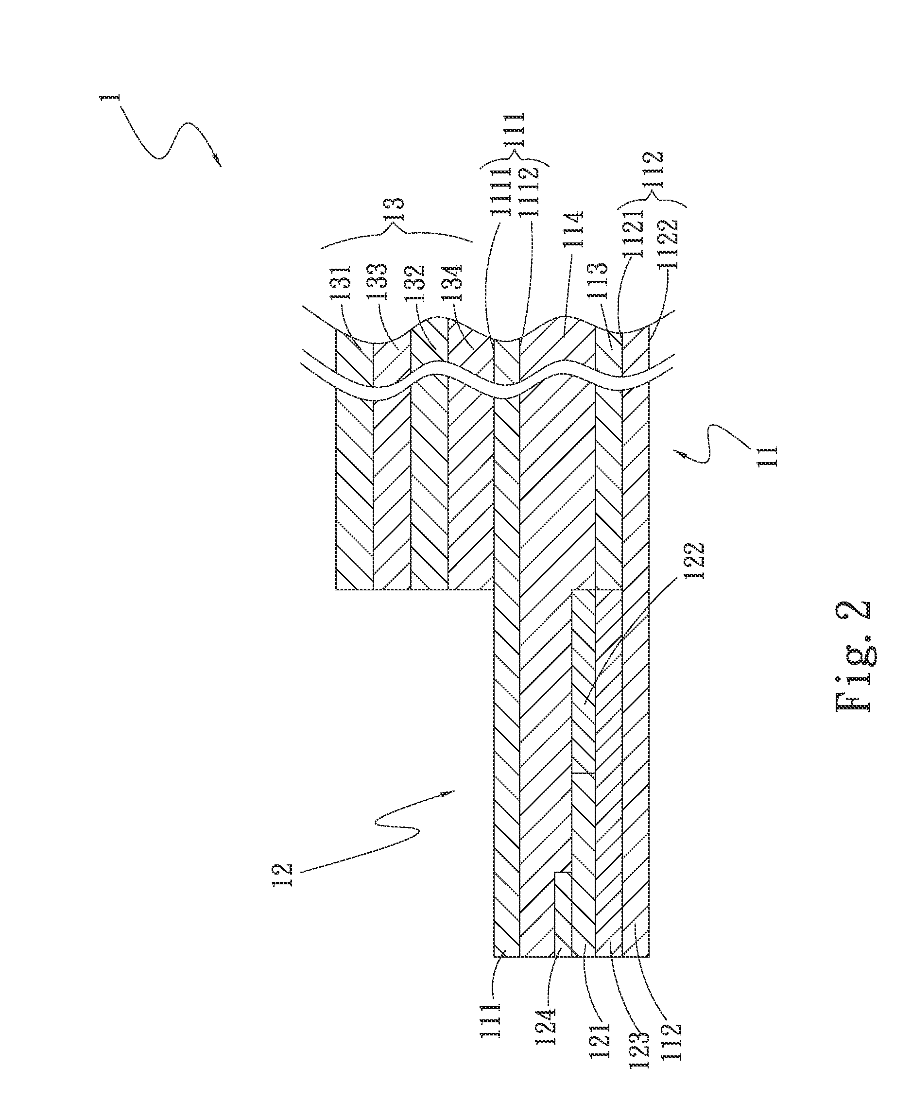
[0015]Please refer to FIG. 1 that is a top view of a touch device with photovoltaic conversion function according to the present invention, and to FIG. 2 that is an assembled sectional view showing the structure of the touch device of the present invention thereof. As shown, the touch device with photovoltaic conversion function includes a main body 1, which is divided into a touch zone 11 and a non-touch zone 12 located immediately around the touch zone 11. A photovoltaic conversion layer 13 is provided on a top of the touch zone 11.

[0016]The main body 1 includes a first transparent substrate 111, a second transparent substrate 112, at least one touch electrode layer 113, an adhesive layer 114, a conductive adhesive layer 121, a shielding layer 122, an electrode trace layer 123, and a flexible circuit board 124.

[0017]The first transparent substrate 111 has a first side 1111 and an opposite second side 1112; and the second transparent substrate 112 has a third side 1121 and an oppo...

fourth embodiment

[0022]The photovoltaic conversion layer 13 in each of the first, the second, the third and the fourth embodiment includes an anti-reflective layer 131 and a light-absorption layer 132. A first transparent electrode layer 133 and a second transparent electrode layer 134 are provided on two opposite sides of the light-absorption layer 132, and the anti-reflective layer 131 is located on one side of the first transparent layer 133 opposite to the light-absorption layer 132. In the present invention, the photovoltaic conversion layer 13 is a thin-film solar cell.

[0023]In the present invention, the first and the second transparent substrate 111, 112 can be respectively made of polyethylene terephthalate (PET), polycarbonate (PC), polyethylene (PE), polyvinylchloride (PVC), polypropylene (PP), polystyrene (PS), polymethylmethacrylate (PMMA), cyclo olefin copolymer (COC) or glass. In the first embodiment, the first transparent substrate 111 is glass while the second transparent substrate 1...


PUM


Abstract

A touch device with photovoltaic conversion function includes a main body divided into a touch zone and a non-touch zone located immediately around the touch zone. A photovoltaic conversion layer is provided on a top of the touch zone. By providing the photovoltaic conversion layer on the top of the touch zone of the touch device, the photovoltaic conversion layer can have an increased light-absorption area to enable conversion of more light into more electric current for use by the touch device and accordingly, enable the touch device to have extended standby and operation time.

Description

This application claims the priority benefit of Taiwan patent application number 101141314 filed on Nov. 7, 2012. FIELD OF THE INVENTION[0001]The present invention relates to a touch device with photovoltaic conversion function, and more particularly to a touch device that includes a photovoltaic conversion layer provided on a top of a touch zone thereof, so that the photovoltaic conversion layer has an increased light-absorption area to convert more light into more electric current for use by the touch device, enabling the touch device to have effectively extended standby and operation time.BACKGROUND OF THE INVENTION[0002]Power supply plays a very important role in the length of standby and operation time of a general portable electronic device. The currently available portable electronic devices rely on the electric power supplied by their built-in battery to maintain operation thereof. For a portable electronic device that includes a touch device, more power will be consumed dur...

Claims


Application Information

Patent Timeline
IPC IPC(8): H05K7/00H01L31/04
CPCH01L31/04H05K7/005H01L31/0488Y02E10/50G02F1/13338H04M19/08G06F1/3262H04M1/0202
Inventor LIN, CHIH-CHUNG
Owner CHIH CHUNG LIN
Why Eureka
Try Eureka