Method of estimating magnet temperature for rotary electric machinery

a technology of rotary electric machinery and estimating method, which is applied in the direction of temperature measurement, heat measurement, instruments, etc., can solve the problems of increasing cost, deteriorating accuracy of estimating method, and difficult heat transfer from stator coils to magnets, so as to achieve easy and accurate calculation of flow rate and improve estimation accuracy , the effect of improving accuracy

Active Publication Date: 2014-05-08
HONDA MOTOR CO LTD
View PDF35 Cites 23 Cited by
  • Summary
  • Abstract
  • Description
  • Claims
  • Application Information

AI Technical Summary

Benefits of technology

[0028]In this case, if a flow rate map, which is representative of a relationship between the rotational speed of the rotating member and the flow rate, is stored in the storage unit, and the dissipation heat calculator determines the flow rate corresponding to the rotational speed by referring to the flow rate map, the flow rate can be calculated easily and accurately, and therefore, the dissipation heat amount can be calculated with greater precision. Further, when a vehicle having the rotary electric machine mounted therein is running, even in the event that the rotary electric machine is operated in a complex manner due to the way in which the vehicle is running, by determining the flow rate corresponding to the rotational speed with reference to the flow rate map, the magnet temperature can be estimated with good estimation accuracy.
[0029]In the present invention, in the event that the rotary electric machine is accommodated in a casing, a bottom of the casing is formed as a drain in which the coolant that has cooled the rotating member is stored. A temperature sensor, which detects the temperature of the

Problems solved by technology

More specifically, if the temperature of the stator coils is higher than the magnet temperature, heat cannot be radiated from the magnets to the stator coils, and as a result, the accuracy with which the magnet temperature is estimated becomes deteriorated, and there is a concern that the magnet temperature will be estimated to be higher than the actual magnet temperature.
With an actual rotary electric machine, since the stator and the rotor are

Method used


Image

  • Method of estimating magnet temperature for rotary electric machinery
  • Method of estimating magnet temperature for rotary electric machinery
  • Method of estimating magnet temperature for rotary electric machinery

Examples


Embodiment Construction

[0046]A method of estimating a magnetic temperature according to a preferred embodiment of the present invention will be described in detail below with reference to FIGS. 1 through 12.

[General Structure of Vehicle that Incorporates a Rotary Electric Machine Therein]

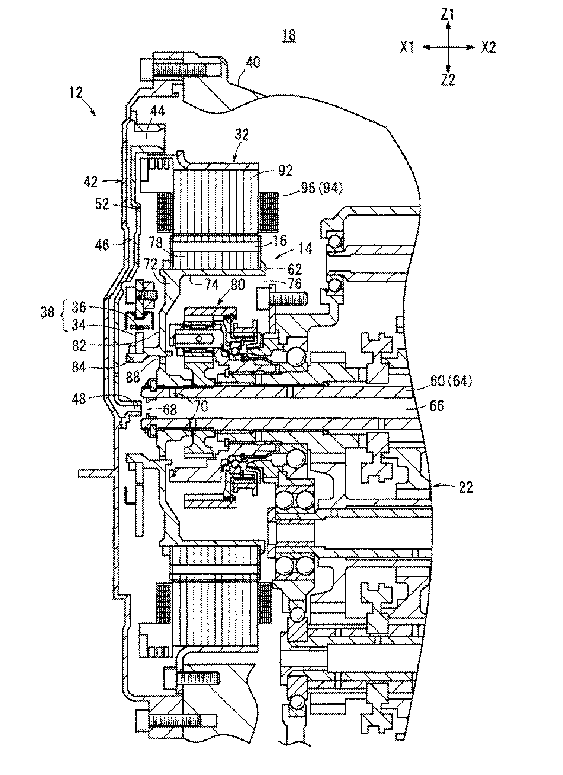
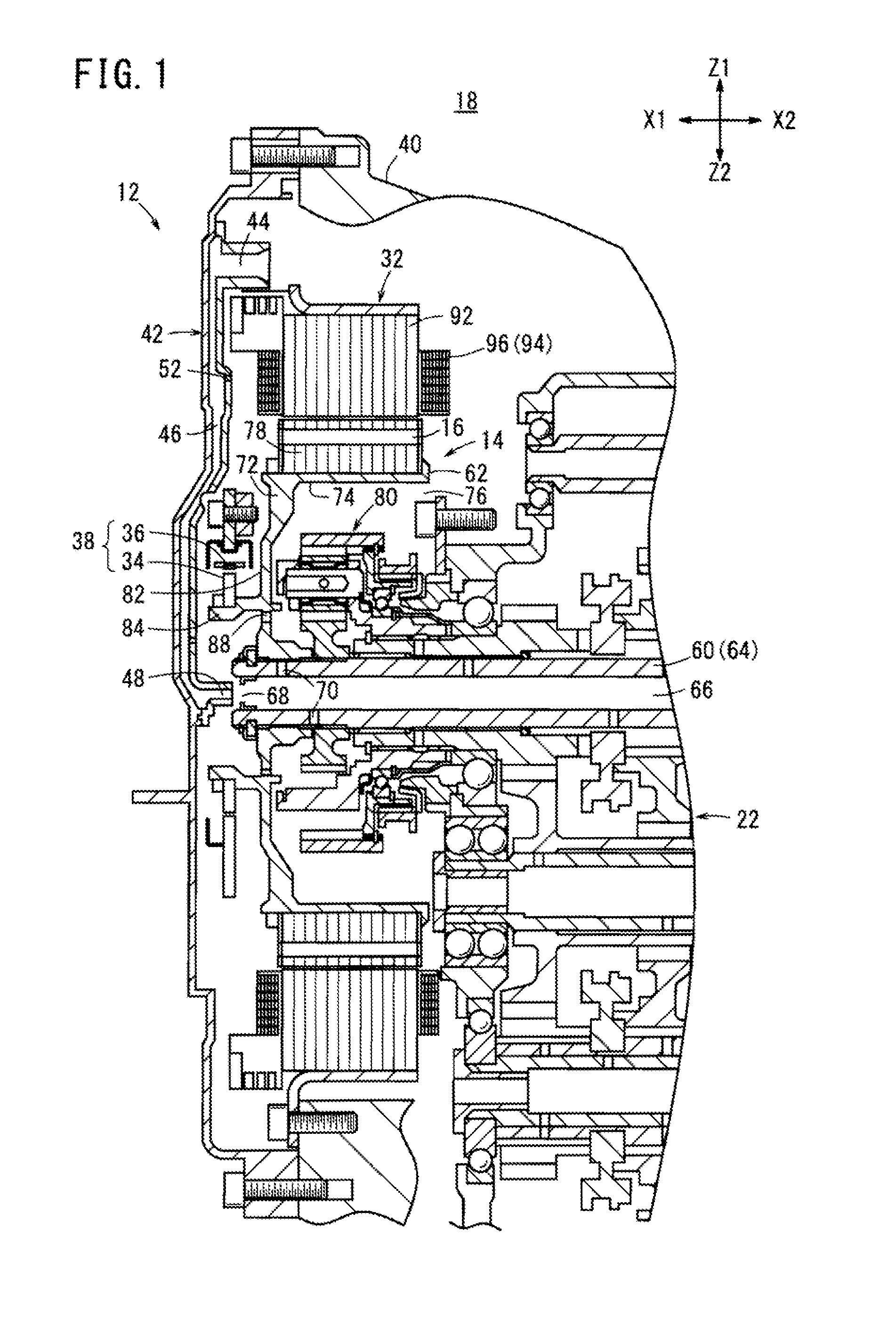
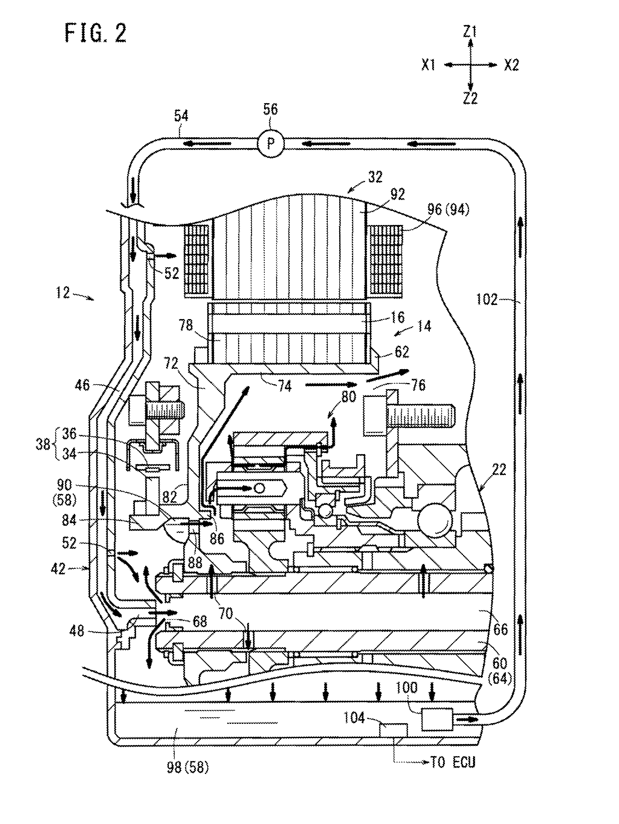
[0047]A magnet temperature estimating apparatus 10 (see FIG. 4), which carries out the method of estimating a magnetic temperature according to the present embodiment, serves as an apparatus for estimating the temperature TMAG of magnets 16 (hereinafter referred to as a “magnet temperature TMAG”) on a rotor 14 (rotating member) of a rotary electric machine 12. The rotary electric machine 12, which includes magnets 16 the temperature of which is to be estimated, is incorporated in a vehicle 18 such as a hybrid vehicle or an electric vehicle.

[0048]FIG. 4 shows the vehicle 18 in the form of a hybrid vehicle, for example. The vehicle 18 has an engine 20 and a transmission 22, with a clutch 24 disposed between the engine 20 an...


PUM


Abstract

In a magnet temperature estimating method, in the event that a rotor of a rotary electric machine is cooled by a cooling oil, a magnet temperature calculator estimates the magnet temperature of magnets provided on the rotor, based on losses of the rotary electric machine including a loss of the rotor and the temperature of the cooling oil.

Description

CROSS-REFERENCE TO RELATED APPLICATION[0001]This application is based upon and claims the benefit of priority from Japanese Patent Application No. 2012-243067 filed on Nov. 2, 2012, the contents of which are incorporated herein by reference.BACKGROUND OF THE INVENTION[0002]1. Field of the Invention[0003]The present invention relates to a method of estimating the temperature of magnets (hereinafter referred to as a “magnet temperature”) on a rotating member of a rotary electric machine.[0004]2. Description of the Related Art[0005]Rotary electric machines include a rotor and a stator that include magnets. When the temperatures of the rotor and the stator exceed a threshold temperature, the magnets start to become demagnetized. Therefore, it is necessary to appropriately manage the temperatures of the rotor and the stator in order to prevent the rotor and the stator from exceeding the threshold temperature. In order to carry out such temperature management, it is desirable to directly ...

Claims


Application Information

Patent Timeline
IPC IPC(8): G01K7/36
CPCG01K7/36G01K13/08G01K7/427Y02T10/641
Inventor ITO, YUTAOYA, SATOYOSHI
Owner HONDA MOTOR CO LTD
Why Eureka
Try Eureka