Turbocharger

a technology of turbocharger and oil tank, which is applied in the direction of positive displacement liquid engine, piston pump, machine/engine, etc., can solve the problems of reducing increasing the limit of the supply pressure of oil, and reducing the pressure of the oil film between the components. , to achieve the effect of minimizing the entry of minute foreign matter

Active Publication Date: 2014-05-08
IHI CORP
View PDF2 Cites 12 Cited by
  • Summary
  • Abstract
  • Description
  • Claims
  • Application Information

AI Technical Summary

Benefits of technology

[0009]A fluid bearing includes a bearing member such as a semi-floating metal disposed between a rotating shaft and a housing, and is designed to form an oil film by forcing oil into the clearance between the housing and the bearing member at a high pressure, and to form an oil film by forcing the oil into the clearance between the rotating shaft and the bearing member at a high pressure. The formation of the oil films between these components as described above enables the rotating shaft to rotate at a high speed.
[0012]The present invention has been made in view of the above-mentioned problems. An object of the present invention is to provide a turbocharger which employs a fluid bearing to support a rotating shaft that connects a turbine and a compressor to each other, and is capable of minimizing the entry of minute foreign matter into the fluid bearing without blocking a function of the fluid bearing.
[0022]According to the present invention, it is possible to provide a turbocharger which employs a fluid bearing to support a rotating shaft that connects a turbine and a compressor to each other, and is capable of minimizing the entry of minute foreign matter into the fluid bearing without blocking a function of the fluid bearing.

Problems solved by technology

Accordingly, a particular problem seems not to occur even when the oil is supplied through the detour where the filter is disposed.
If a filter as in the related art is provided for such a fluid bearing, the filter causes a reduction of pressure, which may complicate the formation of the oil films between the components.
For this reason, the increase range in the supply pressure of the oil is limited.
On the other hand, if the screen of the filter is made coarse, then foreign matter is more likely to flow into the fluid bearing side.
In this context, the filter method is not always effective in order to remove the foreign matter from the oil inside the turbocharger that employs the fluid bearing.
In addition, if the filter method is employed, it is necessary to conduct maintenance work such as the replacement or cleaning of the filter due to the necessity of disposing the filter in an oil supply path.
Accordingly, each clearance between the components is so small that the entry of even minute foreign matter may cause a trouble.
To be more precise, the minute foreign matter moving between the components may damage opposed surfaces of the components or the minute foreign matter stuck between the components may block a flow of the oil between the components.
The occurrence of these phenomena may lead to seizure due to the shortage of the oil or the locking of the rotating shaft, and may cause a reduction in supercharging pressure or the occurrence of abnormal noise from the turbocharger.

Method used


Image

  • Turbocharger
  • Turbocharger
  • Turbocharger

Examples


Embodiment Construction

[0031]An embodiment of the present invention will be described below with reference to the accompanying drawings. To make the descriptions understood easily, the same constituents in the drawings are denoted by the same reference numerals as much as possible and overlapped descriptions will be omitted.

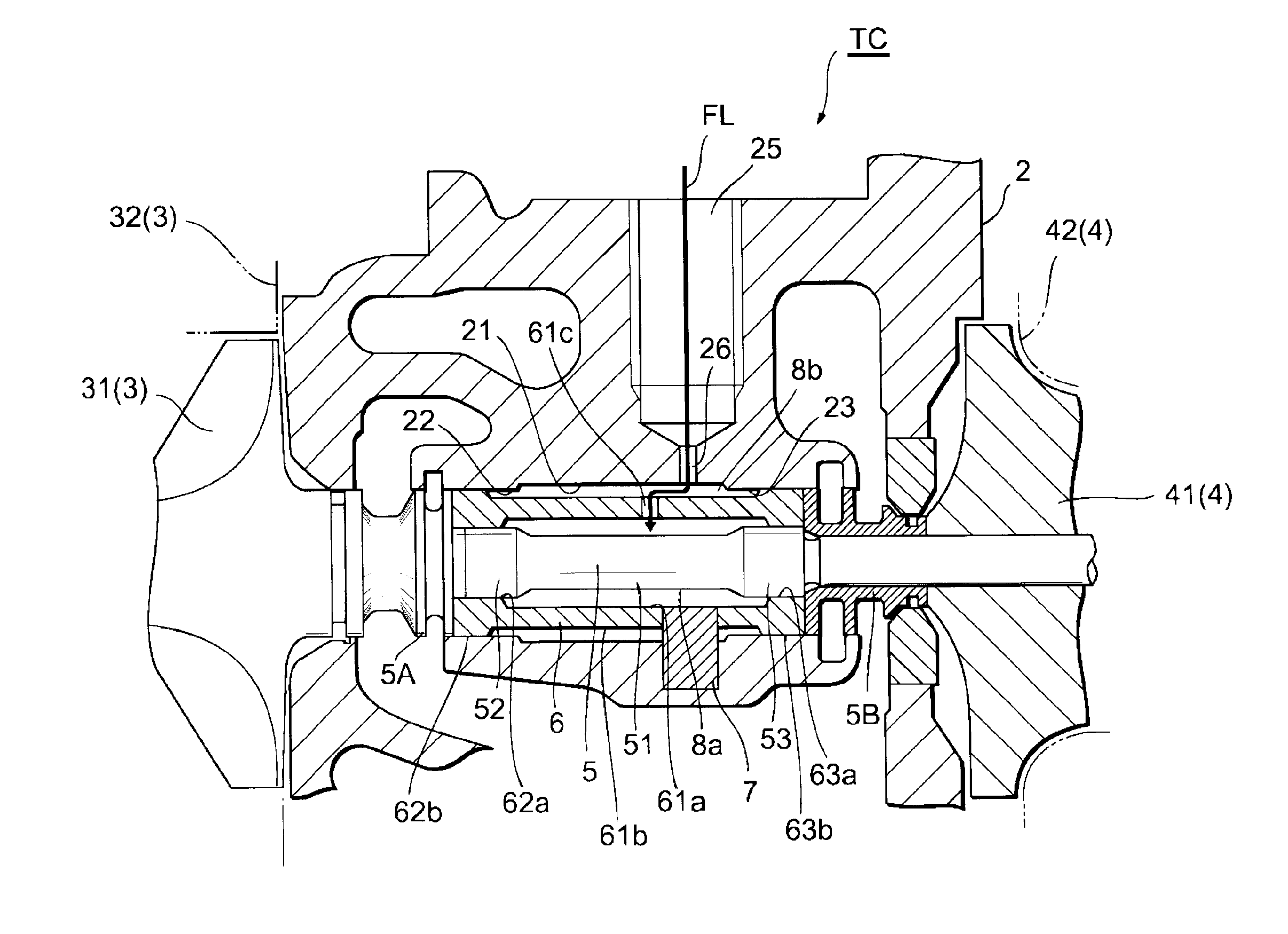
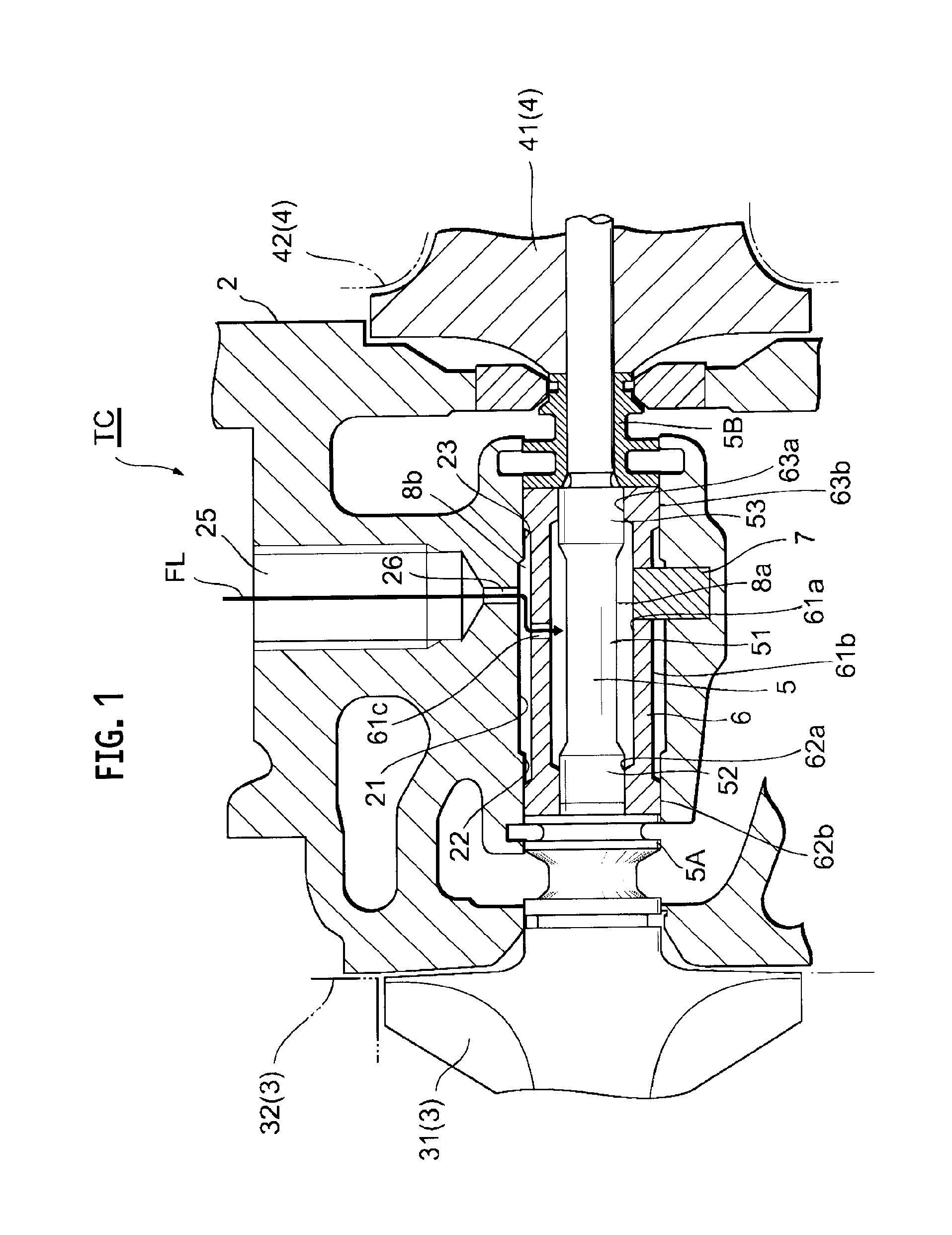
[0032]A turbocharger representing an embodiment of the present invention will be described with reference to FIG. 1. FIG. 1 is a schematic cross-sectional view of a turbocharger TC which is the embodiment of the present invention. As shown in FIG. 1, the turbocharger TC of the embodiment includes a bearing housing 2, a turbine 3 provided with a turbine wheel (turbine impeller) 31, a compressor 4 provided with a compressor wheel (compressor impeller) 41, a rotating shaft 5, and a semi-floating metal 6.

[0033]The turbine wheel 31 is a key component that constitutes the turbine 3, and is housed in a turbine housing 32. The compressor wheel 41 is a key component that constitutes the compres...


PUM


Abstract

A turbocharger includes a semi-floating metal. The semi-floating metal is provided with a supply opening configured to supply oil to an inner bearing section. The turbocharger is provided with: an oil supply path which extends from inside of a bearing housing to the supply opening, and feeds the oil to be supplied to the inner bearing section; a removal section which changes a flowing direction of the oil supplied from an upstream side to separate minute foreign matter in the oil; and a conveyance path and a retaining region which collect the minute foreign matter separated by the removal section so as to prevent the minute foreign matter from mixing again with the oil flowing toward the supply opening.

Description

CROSS REFERENCE TO RELATED APPLICATIONS[0001]This application is a continuation application of International Application No. PCT / JP2012 / 065700, filed on Jun. 20, 2012, which claims priority to Japanese Patent Application No. 2011-153466, filed on Jul. 12, 2011, the entire contents of which are incorporated by references herein.BACKGROUND OF THE INVENTION[0002]1. Field of the Invention[0003]The present invention relates to a turbocharger which includes a turbine and a compressor.[0004]2. Description of the Related Art[0005]A turbocharger including a turbine and a compressor has been widely used as a supercharger for improving a performance of an internal combustion engine. In the turbocharger, a turbine wheel (turbine impeller) constituting the turbine and a compressor wheel (compressor impeller) constituting the compressor are connected to each other by a rotating shaft. An exhaust gas from the internal combustion engine is fed into the turbine side. The exhaust gas thus fed rotates...

Claims


Application Information

Patent Timeline
Patent Type & Authority Applications(United States)
IPC IPC(8): F01D25/18F16C32/06F02C6/12
CPCF16C32/0629F02C6/12F01D25/186F01D25/166F01D25/18F02B39/14F05D2220/40F05D2260/607F05D2240/53F05D2260/604F16C17/18F16C33/105F16C2360/24F16C27/02F16C17/10
Inventor TAKAHASHI, MASASHIGETAKAHASHI, YUKIO
Owner IHI CORP
Why Eureka
Try Eureka