Fuel cell and fuel cell system

a fuel cell and fuel cell technology, applied in the field of fuel cells, can solve the problems of occupying a large space, unable to achieve practicably extremely difficult to realize the airtight sealing space from which the fuel gas does not escape, so as to achieve efficient heating and maintain sealing properties.

Active Publication Date: 2014-05-08
CONNEXX SYST
View PDF13 Cites 18 Cited by
  • Summary
  • Abstract
  • Description
  • Claims
  • Application Information

AI Technical Summary

Benefits of technology

[0010]Moreover, JP 4821937 B describes that if the space between the fuel electrode and the hydrogen-generating member is made into a completely sealed space, hydrogen and water do not need to be replenished from the outside, and a repeatedly usable fuel cell can be realized. The “completely sealed space” mentioned herein, which is a strict requirement relating to air-tightness, is not necessary for conventional fuel cells. This is because in the conventional fuel cells, the fuel gas is continuously supplied, and even if the fuel gas slightly leaks outside the system, it influences the power generation ability to a small extent.
[0014]Moreover, since the above fuel cells are sealed systems, mechanical failure easily occurs due to the change in the internal pressure, and the conventional inventions have proposed iron powder, solid-state carbon, and the like as anode fuel material. However, there has been a demand for the use of metal scrap, solid organic substances such as household waste, and the like, which can be more easily obtained, as the anode fuel material.
[0015]Based on the above circumstances, a first object of the present invention is to provide a compact fuel cell which can efficiently perform heating and in which a space taken up by a thermal insulating material is reduced. Moreover, a second object of the present invention is to provide a fuel cell which makes it possible to seal a closed space of gas in a high temperature region and has a sealing portion that can be repeatedly opened and closed. In addition, a third object of the present invention is to provide a fuel cell which has a pressure-regulating mechanism that can maintain a pressure of the closed space of gas within a predetermined range during operation. Further, a fourth object of the present invention is to provide a fuel cell which can generate power by using, as anode fuel material, a substance such as metal scrap, solid or liquid organic compounds such as household waste, and the like which is introduced from the outside of the fuel cell, and water.
[0030]According to the present invention, a compact fuel cell which can efficiently perform heating can be provided.
[0031]Moreover, according to the present invention, a fuel cell which can maintain sealing properties of a closed space of gas even in a high temperature region and has a sealing portion that can be repeatedly opened and closed can be provided.

Problems solved by technology

However, actually, being high-temperature type cells, these cells require not only a power generation mechanism but also a heating mechanism and a heat-retention mechanism, and this leads to a problem that they take up much space.
However, in a solid oxide fuel cell operated particularly at a high temperature of about 300° C. to 1,000° C., it is practically extremely difficult to realize the airtight sealed space from which the fuel gas does not leak.
In a region of a high temperature exceeding 300° C., it is impossible to use heat-resistant rubber or a gasket made of an organic substance that is usually used for realizing airtight sealed spaces, and usable sealing means are limited to a metal gasket, ceramic paste, and the like.
The reason why the airtightness is not easily secured in a high temperature region is that, for example, since the materials to be connected and the sealing material have different thermal expansion coefficients, when the temperature is increased, the airtightness is impaired due to the expansion and rupture of the sealing material.
The conventional airtightness maintaining method that seals the high-temperature portion by using metals, ceramics, molten glass, and the like has a high possibility that the airtightness may deteriorate due to the repetition of expansion and contraction of the materials and lacks reliability.
In addition, when the solid oxide fuel cell is repeatedly operated at a high temperature of about 300° C. to 1,000° C., the solid oxide itself does not endure thermal impact and cracks in many cases.
Similarly to the sealing material, if the solid oxide itself cracks, the airtightness of the sealed space is impaired.

Method used


Image

  • Fuel cell and fuel cell system
  • Fuel cell and fuel cell system
  • Fuel cell and fuel cell system

Examples


first embodiment

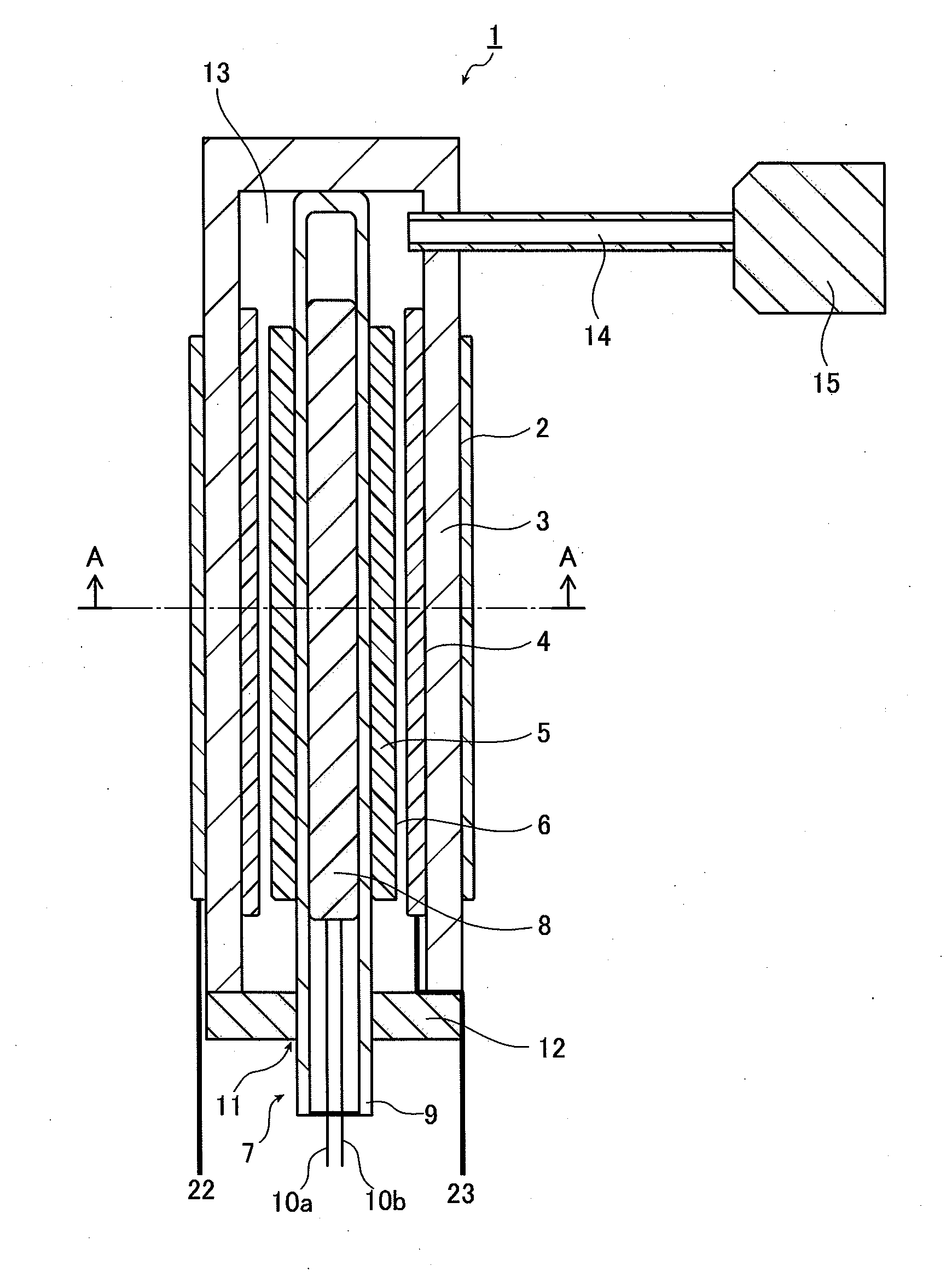
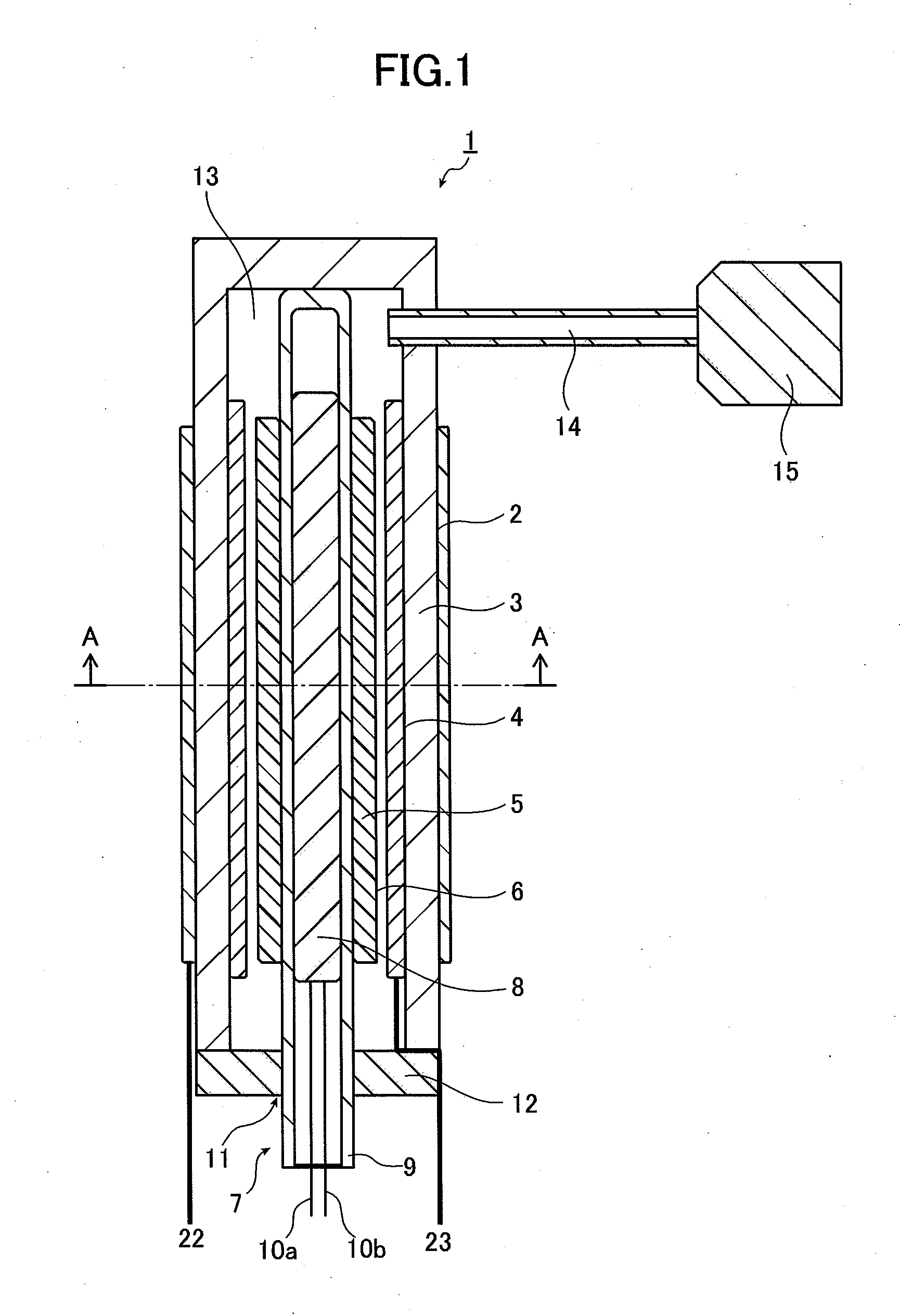
[0055]FIG. 1 shows the entire constitution of a fuel cell 1 according to the first embodiment of the present invention, and

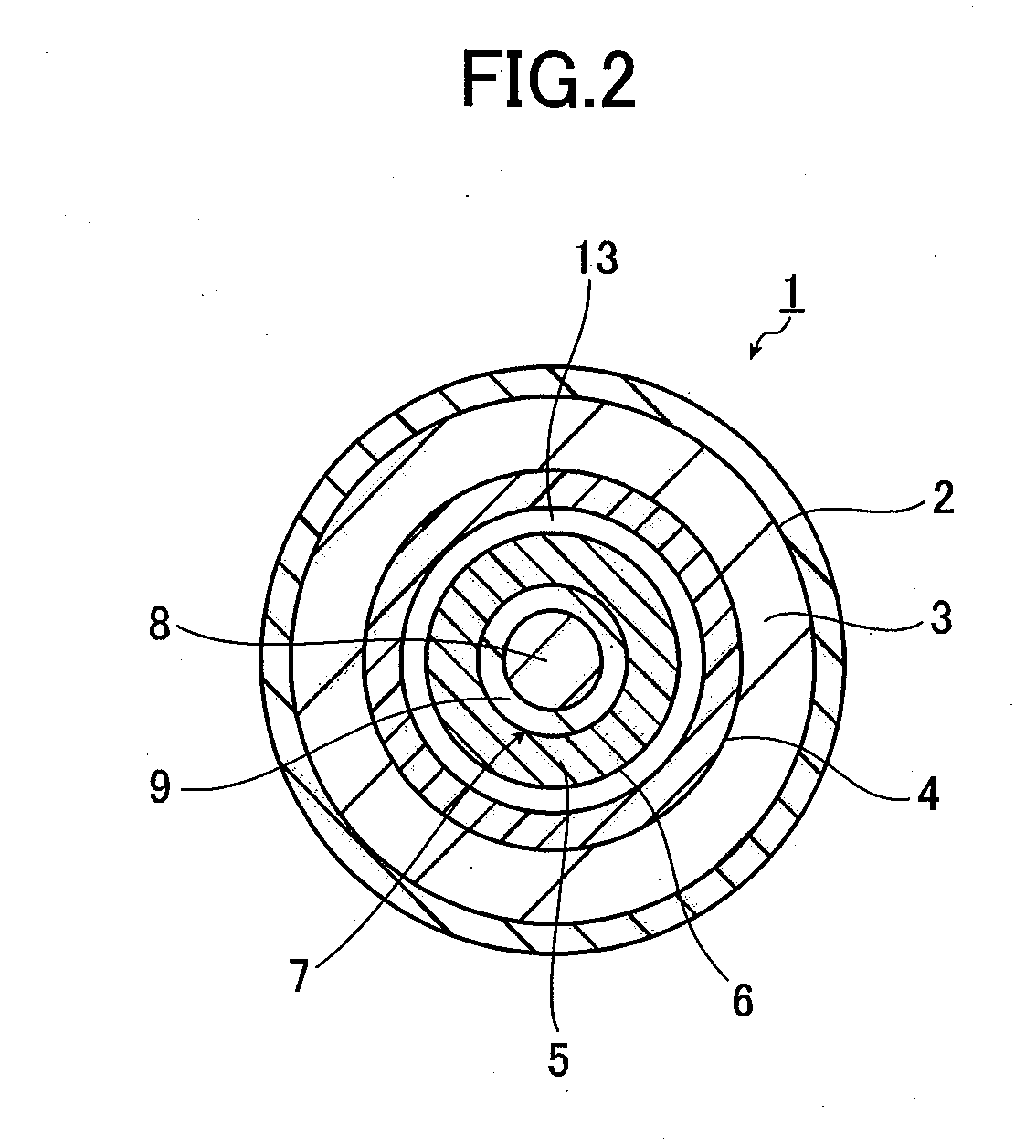
[0056]FIG. 2 shows a cross-sectional view obtained when the fuel cell 1 of FIG. 1 is cut along the cross-section A-A.

[0057]As FIGS. 1 and 2 clearly show, the fuel cell 1 includes a cathode 2, a solid electrolyte 3, an anode 4, and an anode fuel material 5 (and an anode fuel case 6) that are each formed in a cylindrical shape, in this order from the outside, and includes a heating portion 7 at the center of the anode fuel material 5.

[0058]The cathode 2, the solid electrolyte 3, and the anode 4 are in close contact with one another, and between the anode 4 and the anode fuel material 5 (and the anode fuel case 6), a predetermined gap is disposed so as to prevent the anode 4 and the anode fuel material 5 from coming into contact with each other.

[0059]One end of the cylindrical solid electrolyte 3 is blocked, the other end thereof is provided with a cap 12 having a ...

second embodiment

[0093]In the first embodiment, the other end of the cylindrical solid electrolyte 3 of which one end is blocked is sealed with the cap 12, whereby the sealed space 13 in which the anode 4 and the anode fuel material 5 are sealed is formed.

[0094]Moreover, in the first embodiment, for generating power, the fuel cell 1 (the cathode 2, the solid electrolyte 3, the anode 4, and the anode fuel material 5) is heated by the heating portion 7 up to about 850° C. to 1,000° C. Therefore, with sealing means that is easily opened and closed, the sealed state of the sealed space 13 cannot be thoroughly maintained.

[0095]Accordingly, for example, in the constitution of the first embodiment, if the sealed space 13 is sealed by sealing means premised on the replacement of the anode fuel material 5, the space is not sufficiently sealed, so a life of the fuel cell is shortened.

[0096]A fuel cell 101 according to the second embodiment is a countermeasure for the above problems that the above sealing mean...

third embodiment

[0106]In the second embodiment, the heating portion 7 (particularly, the heating element 8) is separated from the sealing portion 16 by a predetermined distance L to form a space (temperature transition region), so as to improve the durability of the body of the fuel cell 101. As shown in FIG. 5, in addition to the constitution of the second embodiment, a thermal insulating material 26 may be installed in a fuel cell 201 so as to cover the solid electrolyte 3 that extends from the end of the cathode 2 (near the heating element 8 of the heating portion 7) to the sealing portion 16 at the other end of the solid electrolyte 3. In the solid electrolyte 3 of FIG. 5, the portion corresponding to the heating element 8 is a heating region, the portion from the end of the heating element 8 to the end of the sealing portion 16 is a temperature transition region, and the portion corresponding to the sealing portion 16 is a sealing region.

[0107]The thermal insulating material 26 is constituted ...


PUM

PropertyMeasurementUnit
temperatureaaaaaaaaaa

Abstract

The compact fuel cell which can efficiently perform heating and can be repeatedly used includes a solid electrolyte, an anode that is formed on one surface of the solid electrolyte, a cathode that is formed on another surface of the solid electrolyte, an anode fuel material, a heating portion for heating and maintaining the solid electrolyte and the anode fuel material at a temperature equal to or higher than a predetermined level, and a sealing portion that is installed in the solid electrolyte, forms a sealed space sealing the anode and the anode fuel material together with the solid electrolyte and the heating portion, and can repeatedly open and close, in which a helium leak rate of the sealed space is maintained at 1×10⁻² Pa·m3 / sec or a lower rate.

Description

BACKGROUND OF THE INVENTION[0001]The present invention relates to a fuel cell which is useful as a stationary power source or a power source for moving objects such as cars, and as a portable power source. Particularly, the present invention relates to a fuel cell having a fuel gas regeneration apparatus and a fuel cell system using the fuel cell.[0002]A fuel cell is means for generating power by supplying fuel gas. The fuel cell is expected to be applicable as a stationary middle-sized energy storage apparatus or as a driving source for electric cars or hybrid cars. Moreover, research and development are in progress so as to use the fuel cell as a power source for portable instruments such as mobile phones and laptop computers by realizing weight lightening and miniaturizing of the fuel cell.[0003]Since the efficiency of electric energy obtained from a fuel cell is high in principle, it could be an efficient energy storage device if energy can be saved. In addition, since the fuel ...

Claims


Application Information

Patent Timeline
Patent Type & Authority Applications(United States)
IPC IPC(8): H01M8/04H01M8/12
CPCH01M8/12H01M8/04007H01M8/004H01M8/006H01M8/0271H01M8/0278H01M8/1246H01M8/2425H01M8/243H01M2008/1293H01M8/124H01M8/1253H01M8/126H01M8/1266Y02E60/50Y02P70/50
Inventor KACHI, NAOYOSHI
Owner CONNEXX SYST
Why Eureka
Try Eureka