
Transcatheter Valve Prosthesis Delivery System With Recapturing Feature and Method

a technology of transcatheter valve and delivery system, which is applied in the field of systems and methods for percutaneous implantation of heart valve prosthesis, can solve the problems of life-threatening complications, long recovery time, and many patients requiring cardiac valve replacement are deemed to pose too high a risk for open heart surgery

Active Publication Date: 2014-05-08
MEDTRONIC INC
View PDF19 Cites 44 Cited by
  • Summary
  • Abstract
  • Description
  • Claims
  • Application Information

AI Technical Summary

Benefits of technology

The patent describes a delivery system for valve prostheses that has a stable handle and a capsule for holding the prosthesis during delivery. The system uses an oscillating device to induce a vibration on the delivery system, which reduces friction between the prosthesis and the capsule, making it easier to recapture and deploy the prosthesis at the implantation site. The method also involves compressing the valve prosthesis and advancing it to the desired location using the vibration. Overall, this system and method offer a more effective and efficient approach to treating valve disorders in the heart.

Problems solved by technology

Such procedures are traumatic to the patient, require a long recovery time, and can result in life threatening complications.
Therefore, many patients requiring cardiac valve replacement are deemed to pose too high a risk for open heart surgery due to age, health, or a variety of other factors.
If the prosthesis is incorrectly positioned relative to the native annulus, serious complications can result as the deployed device can leak and can even dislodge from the native valve implantation site.
While imaging technology can be employed as part of the implantation procedure to assist a clinician in better evaluating a location of the transcatheter valve prosthesis immediately prior to deployment, in many instances, this evaluation alone is insufficient.
While, in theory, the recapturing of a partially deployed stented valve prosthesis is straight forward, in actual practice, the constraints presented by the implantation site and the stented heart valve itself render the technique exceedingly difficult.
Conversely, however, the component cannot be overly rigid so as to avoid damaging the transcatheter heart valve as part of a recapturing procedure.
Unfortunately, with conventional sheath configurations, attempting to compress the expanded region of the stented valve prosthesis by distally sliding the sheath is unlikely to be successful.
The conventional delivery sheath cannot readily overcome the radial force of the expanded region of the prosthesis because, in effect, the sheath is placed into compression and will collapse due at least in part to the abrupt edge of the sheath being unable to cleanly slide over the expanded region of the prosthesis.

Method used


Image

  • Transcatheter Valve Prosthesis Delivery System With Recapturing Feature and Method
  • Transcatheter Valve Prosthesis Delivery System With Recapturing Feature and Method
  • Transcatheter Valve Prosthesis Delivery System With Recapturing Feature and Method

Examples


Embodiment Construction

[0029]The following detailed description of a valve prosthesis delivery system refers to the accompanying figures that illustrate exemplary embodiments. Other embodiments are possible. Modifications can be made to the embodiments described herein without departing from the spirit and scope of the present invention. Therefore, the following detailed description is not meant to be limiting.

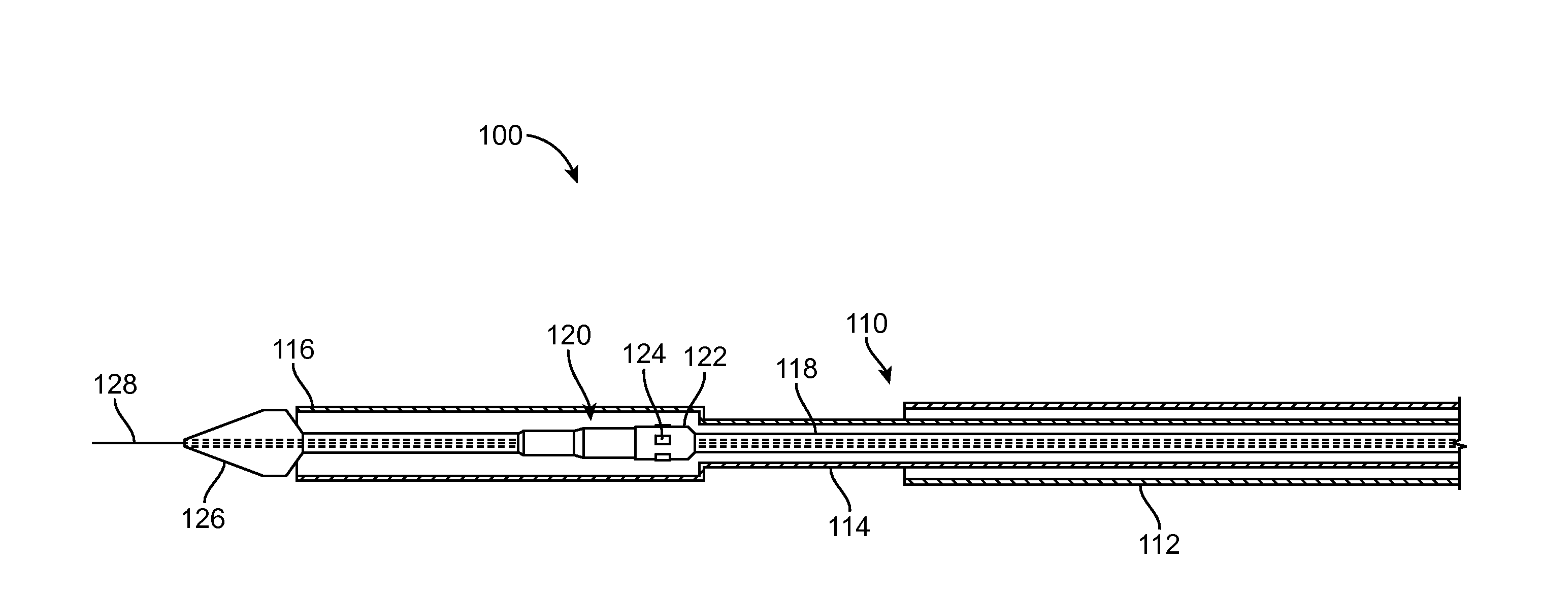
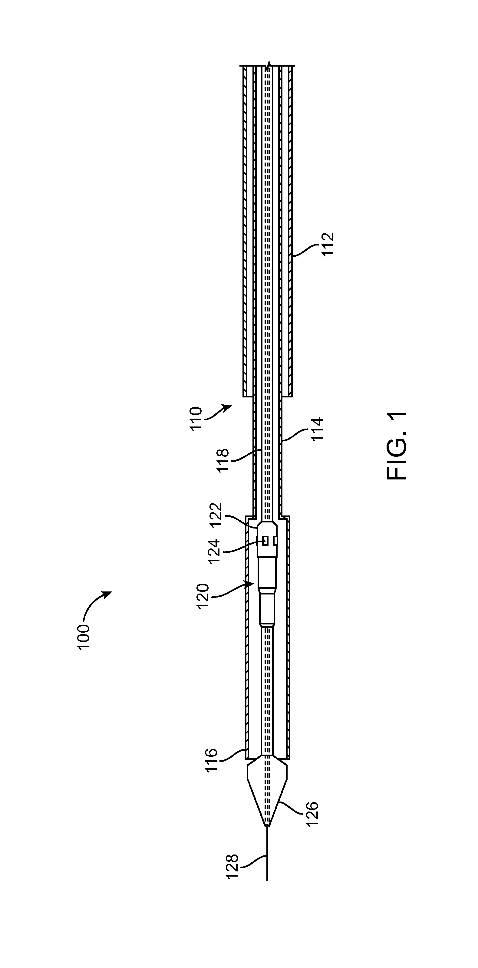
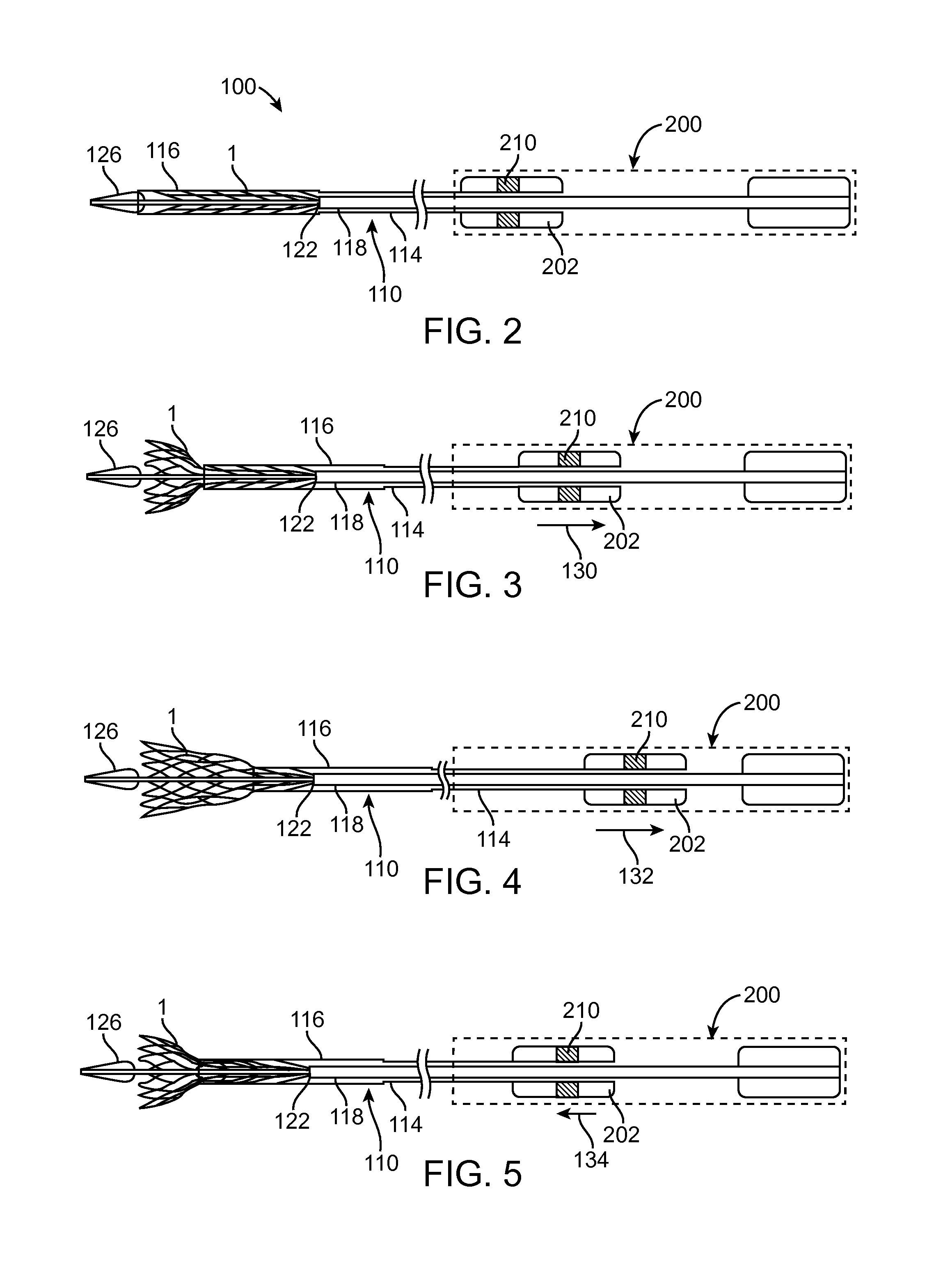
[0030]The present invention is directed to a heart valve prosthesis delivery system including an oscillating device to transmit vibratory motion along the delivery system. The vibratory motion can be used to reduce friction between surfaces, which is commonly known as applying a “dither.” Friction of two objects in vibration can reduce the friction coefficient and friction forces between the two objects, lighten the abrasion between the objects, reduce energy consumption, and greatly increase working efficiency. In the present invention, the recapture forces in the delivery system are reduced by app...


PUM


Abstract

A delivery system for percutaneously deploying a valve prosthesis. The system includes a catheter assembly including a delivery sheath capsule and a handle having an oscillating device. The capsule is configured to compressively retain the valve prosthesis during implantation. After the valve prosthesis is partially exposed during implantation, the oscillating device can create a vibratory motion to reduce the friction between the valve prosthesis and the delivery sheath capsule in order to recapture the valve prosthesis.

Description

BACKGROUND OF THE INVENTION[0001]1. Field of the Invention[0002]The present invention is related to systems and methods for percutaneous implantation of a heart valve prosthesis.[0003]2. Background Art[0004]Cardiac valves exhibit two types of pathologies: regurgitation and stenosis. Regurgitation is the more common of the two defects. Either defect can be treated by a surgical repair.[0005]Under certain conditions, the cardiac valve must be replaced. Standard approaches to valve replacement require cutting open the patient's chest and heart to access the native valve. Such procedures are traumatic to the patient, require a long recovery time, and can result in life threatening complications. Therefore, many patients requiring cardiac valve replacement are deemed to pose too high a risk for open heart surgery due to age, health, or a variety of other factors. These patient risks associated with heart valve replacement are lessened by the emerging techniques for minimally invasive val...

Claims


Application Information

Patent Timeline
IPC IPC(8): A61F2/24
CPCA61F2/966A61F2250/0093A61F2/2436A61F2/9517A61F2/2418
Inventor QUILL, JASONROTHSTEIN, PAULSECORD, THOMASJOHNSON, BYRON
Owner MEDTRONIC INC
Learn More