Power generator

a power generator and power input technology, applied in the direction of motors, machines/engines, mechanical equipment, etc., can solve the problems of reducing the efficiency, and therefore the viability of the system, and generating the power input needed, and achieve the effect of increasing efficiency

Inactive Publication Date: 2014-05-15
ANTEAU MARK R
View PDF6 Cites 18 Cited by
  • Summary
  • Abstract
  • Description
  • Claims
  • Application Information

AI Technical Summary

Benefits of technology

[0006]Exemplary embodiments of the present disclosure pertain to power generation systems of reusable and renewable energy sources, and improvements thereon having increased efficiencies. An object of the invention is to provide an apparatus for generating power from a fluid in a reservoir having a power station, a first return system in fluid receiving connection with a first power chamber of the power station at a first attachment point, a second return system in fluid receiving connection with a second power chamber of the power station at a second attachment point, and a means for reciprocally draining and filling the first and second pontoon chambers of the power station. The power station is further provided with a first power chamber having an external valve actuatable to control flow of the fluid between the reservoir and the first power chamber, a first upper coil tube having fixed and free ends, the fixed end thereof being secured at a first upper seal to an interior wall of the first power chamber, and the free end thereof forming a first movable boundary, a first lower coil tube having fixed and free ends, the fixed end thereof being secured at a first lower seal to the interior wall of the first power chamber below the first upper seal, whereby the first upper seal and the first lower seal define a first pontoon chamber, a first pontoon positioned between the free ends of the first upper coil tube and the first lower coil tube, a second power chamber having an external valve actuatable to control flow of the fluid between the reservoir and the second power chamber, a second upper coil tube having fixed and free ends, the fixed end thereof being secured at a second upper seal to an interior wall of the second power chamber, and the free end thereof forming a second movable boundary, a second lower coil tube having fixed and free ends, the fixed end thereof being secured at a second lower seal to the interior wall of the second power chamber below the second upper seal, whereby the second upper seal and the first lower seal define a second pontoon chamber, a second pontoon positioned between the free ends of the second upper coil tube and the second lower coil tube, a connecting pipe coupled to the first power chamber and the second power chamber, and a constant volumetric flow region defined by the first movable boundary and the second movable boundary, wherein the first and second movable boundaries move synchronously, thereby maintaining the volume of the constant volumetric flow region during movement induced by pressure differentials in the power station.

Problems solved by technology

A particularly salient obstacle to power generation is the power input needed for use in the generation scheme.
The input power required will inherently reduce the efficiency, and therefore the viability of, the system.

Method used


Image

  • Power generator
  • Power generator
  • Power generator

Examples


third embodiment

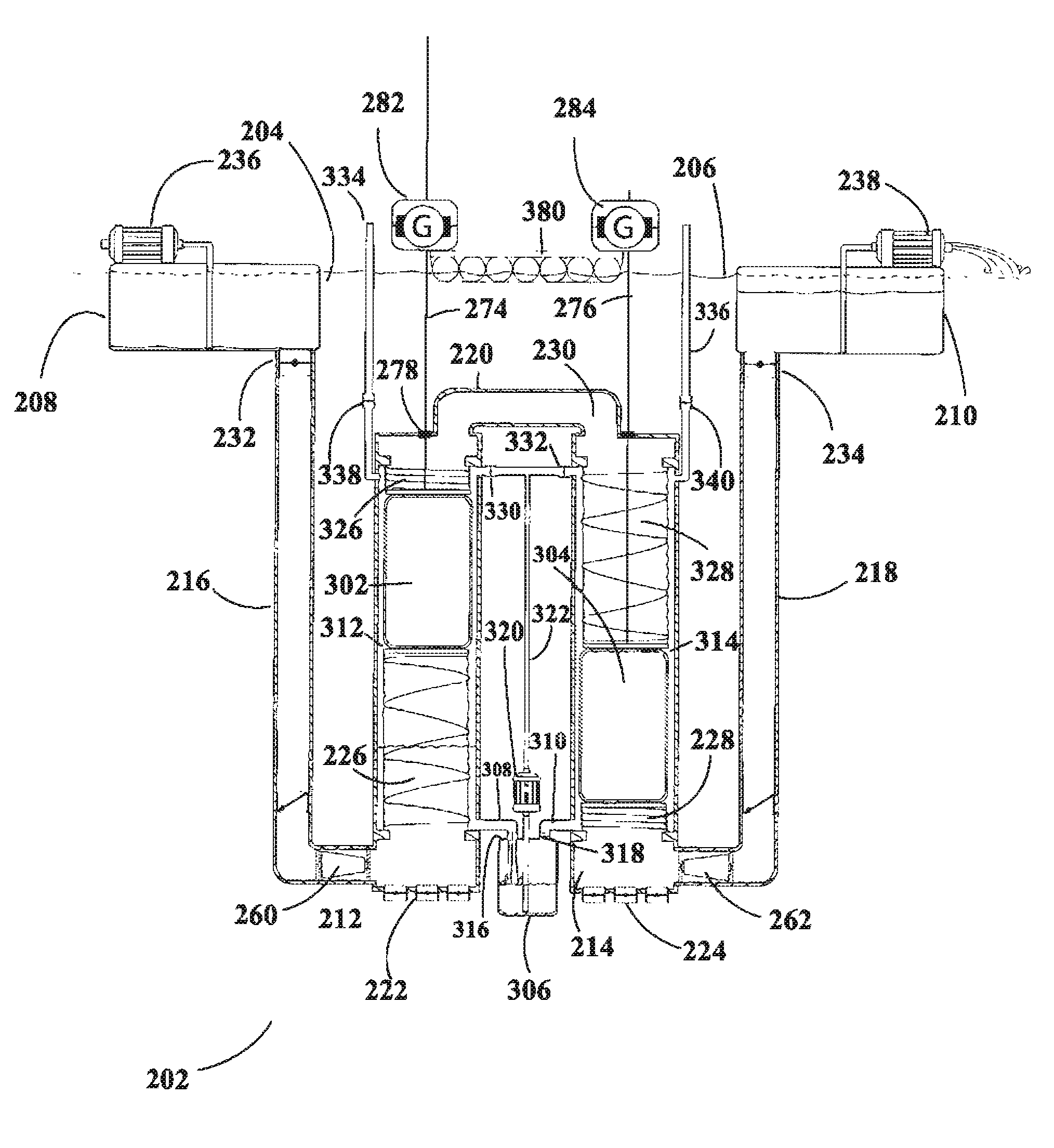
[0089]the apparatus depicted in FIGS. 8-11 utilizes pontoons contained within pontoon chambers to enhance and augment the power derived from the water flowing through the system 202. For relatively little power investment, the pontoons enable the system 102 to greatly augment the work performed by the connecting rods external to the 102.

[0090]FIG. 8 depicts an arrangement similar to that shown in FIGS. 5-7, but with modifications to the regions between the first 216 and second 218 evacuation tubes. The movable extremes of the constant volumetric flow region 230 are rigid plates affixed to and capping the end of a first 326 and second 328 upper pontoon chamber coil tube. As the constant volumetric flow region shifts from one pontoon chamber to the other, the first 326 and second 328 upper pontoon chamber coil tubes alternate in their expansion and contraction, maintaining a constant volume of water within the coil tubes and connecting pipe 220. As in FIGS. 5-7, the first 212 and seco...

exemplary embodiment 2000

[0180]Finally, FIGS. 34-35 illustrate that vertical and horizontal positioning may be interchangeable in the given systems, wherein orientation is not meant to be limiting. In this exemplary embodiment 2000, the constant volumetric region 2002 is defined at movable boundary ends 2004 and 2006 connected by rod 2008. The region 2002 can be air or water filled, and is preferably provided with one or more baffles 2010. The baffles 2010 may be further provided with turbines or other such generators, such as 2012 and 2014. Note that, in this embodiment turbines 2012 allow flow in one direction, and turbines 2014 allow flow in the other. Less or more turbines can be used, in combination with bypass valves as an alternative, for instance. Finally, gate turbines 2016 are placed at the power chamber 2018 and 2020 inlets, which operate with the first 2022 and second 2024 return systems to cycle as previously described herein.


PUM


Abstract

The power plant disclosed is an engine that derives its usefulness in the pursuit of energy generation by utilizing hydrostatic pressure differentials found or created in various liquids, gases or solutions, such as but not limited to water and air. It is generally provided as a two-stroke piston cycle power generating system, wherein the actions of the pistons perform work or replenish working fluid from a lower head to a higher head, and can be utilized to generate power, pump fluids, or perform work, for example. Multiple power generating systems are interconnected to provide continuous and constant power generation through a penstock and turbine system.

Description

CROSS-REFERENCE TO RELATED APPLICATIONS[0001]This application claims priority to, the benefit of, and is a continuation in part of co-pending U.S. patent application Ser. No. 14 / 133,637 filed 18 Dec. 2013, a continuation in part of co-pending U.S. patent application Ser. No. 13 / 537,046 filed 28 Jun. 2012, and also claims priority to and the benefit of co-pending U.S. Provisional Application No. 61 / 755,204 filed 22 Jan. 2013, the content of each of which being hereby incorporated by reference as if fully recited herein.TECHNICAL FIELD[0002]This disclosure relates to the field of power generation, and more specifically to power generation systems and methods based on renewable energy and pressure differential principles.BACKGROUND OF THE INVENTION[0003]As energy sources based on fossil fuels become ever more expensive to maintain and their environmental cost is realized and quantified, the world has turned to renewable energy sources to combat these disadvantages of traditional energy...

Claims


Application Information

Patent Timeline
Patent Type & Authority Applications(United States)
IPC IPC(8): F03B17/00F03B17/02
CPCF03B17/02F03B17/005F03B17/025F03G7/04Y02E10/20
Inventor ANTEAU, MARK R.
Owner ANTEAU MARK R
Why Eureka
Try Eureka