
Printed circuit board and manufacturing method thereof

a technology of printed circuit board and manufacturing method, which is applied in the manufacture of printed circuits, cable/conductor components, and semiconductor/solid-state devices. it can solve the problems of difficult control of plating thickness and reliability of products to be deteriorated, and achieve the effect of preventing non-peeling of dry film and not causing

Inactive Publication Date: 2014-05-22
SAMSUNG ELECTRO MECHANICS CO LTD
View PDF2 Cites 1 Cited by
  • Summary
  • Abstract
  • Description
  • Claims
  • Application Information

AI Technical Summary

Benefits of technology

The present invention is about a printed circuit board that has a symmetrical design and can have uneven plating thickness on the front and back sides. This prevents the dry film from peeling off and causes no short defects. The circuit board is manufactured using a specific method that ensures fine circuit formation.

Problems solved by technology

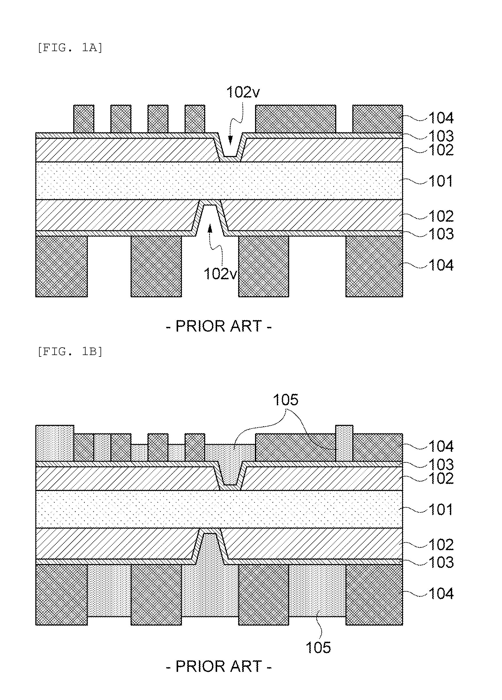
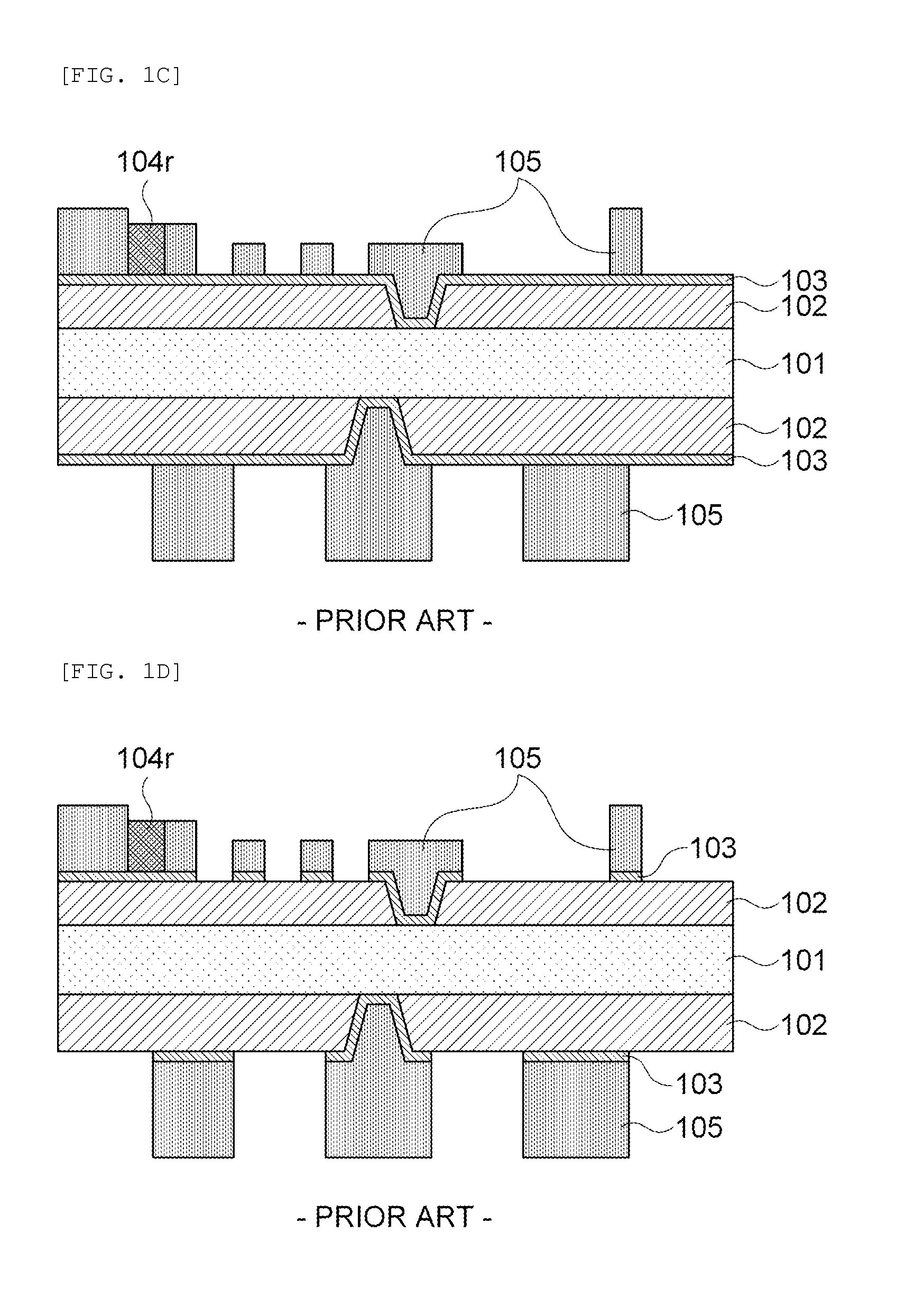
As a result, deviation occurs in the plating thickness, and particularly, the front side is affected by the rear side, such that it is difficult to control the plating thickness.
This leads to defective products and causes reliability of the products to be deteriorated.

Method used


Image

  • Printed circuit board and manufacturing method thereof
  • Printed circuit board and manufacturing method thereof
  • Printed circuit board and manufacturing method thereof

Examples


Embodiment Construction

[0029]The terms and words used in the present specification and claims should not be interpreted as being limited to typical meanings or dictionary definitions, but should be interpreted as having meanings and concepts relevant to the technical scope of the present invention based on the rule according to which an inventor can appropriately define the concept of the term to describe most appropriately the best method he or she knows for carrying out the invention.

[0030]Through the present specification, unless explicitly described otherwise, “comprising” any components will be understood to imply the inclusion of other components but not the exclusion of any other components. The terms “unit”, “module”, “device” or the like means a unit processing at least one function or operation, which may be implemented by a hardware, a software, or combinations of the hardware and the software.

[0031]Hereinafter, embodiments of the present invention will be described in detail with reference to ...


PUM


Abstract

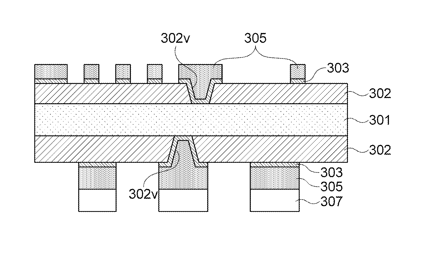
Disclosed herein are a printed circuit board and a manufacturing method thereof. In the manufacturing method of the printed circuit board according to the exemplary embodiment of the present invention, primary copper plating layers are first formed on each of upper and lower surface portions of a core layer in a symmetrical structure, an insulating layer is formed on the primary copper plating layer of the upper surface side, and a secondary copper plating layer is continuously formed on the primary copper plating layer of only the lower surface side. Therefore plating thicknesses required for the front side and the rear side in an asymmetric structure may be uniform to have no plating deviation and non-peeling of an insulating layer (a dry film) for a circuit protection is prevented to have no short defect, thereby making it possible to form a fine circuit pattern.

Description

CROSS REFERENCE(S) TO RELATED APPLICATIONS[0001]This application claims the benefit under 35 U.S.C. Section 119 of Korean Patent Application Serial No. 10-2012-0131549, entitled “Printed Circuit Board and Manufacturing Method Thereof” filed on Nov. 20, 2012, which is hereby incorporated by reference in its entirety into this application.BACKGROUND OF THE INVENTION[0002]1. Technical Field[0003]The present invention relates to a printed circuit board and a manufacturing method thereof, and more particularly, to a printed circuit board of an asymmetric structure formed to have plating thicknesses of a front side and a rear side of the board different from each other and a manufacturing method thereof.[0004]2. Description of the Related Art[0005]As a printed circuit board for a semiconductor has recently been miniaturized and ultra-thinned, a design of the board of an asymmetric structure has been required. Here, the asymmetric structure is a structure formed to have plating thicknesses...

Claims


Application Information

Patent Timeline
Patent Type & Authority Applications(United States)
IPC IPC(8): H05K1/02H05K3/44
CPCH05K3/445H05K1/0201H05K3/108H05K3/4644H05K2203/1476H01L2924/0002H05K2201/0352H01L23/49822H05K1/0209H05K2203/1572H01L2924/00
Inventor KYON, JOHN, SU
Owner SAMSUNG ELECTRO MECHANICS CO LTD
Learn More