Methods of Operation of Fuel Injectors with Intensified Fuel Storage
a fuel storage and fuel injection technology, applied in mechanical equipment, machines/engines, electric control, etc., can solve the problems of system serious drawbacks, unburned fuel levels in the exhaust, loss of compression energy,
- Summary
- Abstract
- Description
- Claims
- Application Information
AI Technical Summary
Benefits of technology
Problems solved by technology
Method used
Image

Examples
Embodiment Construction
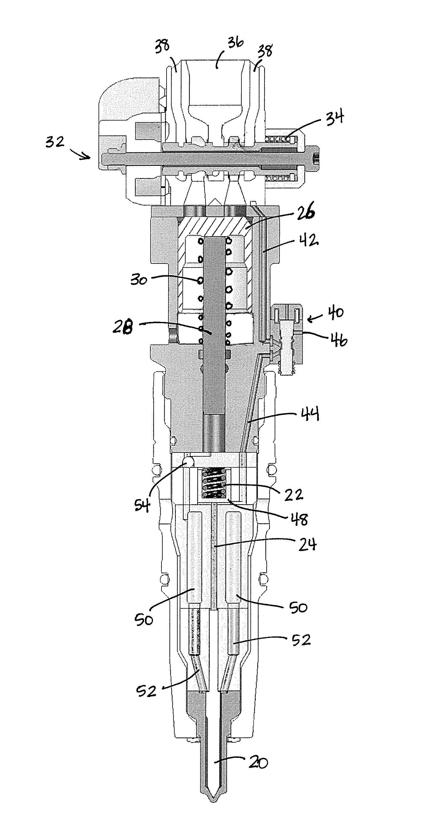
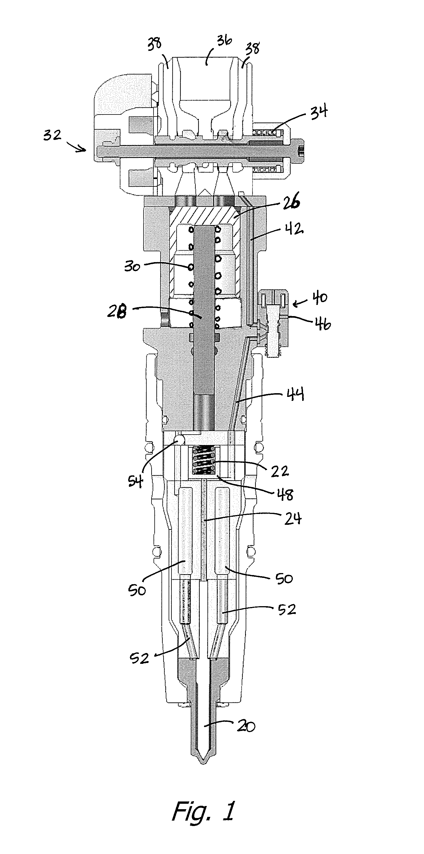
[0011]In accordance with the present invention, the prior art method of intensifying a quantity of fuel and controlling the injection by direct needle control while the intensifier remains activated is modified to intensifying a quantity of fuel, then isolating the intensified fuel from the intensifier and keeping it isolated during subsequent injection events or injection sub-events. Such operation has been found to have a number of advantages over the prior art. Specifically, such operation has been found to control and greatly reduce pressure spikes in the intensified fuel which can cause mechanical deterioration of the injector. Also an injector operating in the prior art manner exhibits an undesired lack of repeatability, perhaps not detectable to one not looking closely, but which is in fact present, limiting the extent to which the performance of each cylinder of a multi-cylinder engine can be equalized. These effects may arise in part from the presence of a valve (preferably...
PUM
 Abstract
Description
Claims
Application Information
 - R&D
- Intellectual Property
- Life Sciences
- Materials
- Tech Scout
- Unparalleled Data Quality
- Higher Quality Content
- 60% Fewer Hallucinations
Browse by: Latest US Patents, China's latest patents, Technical Efficacy Thesaurus, Application Domain, Technology Topic, Popular Technical Reports.
© 2025 PatSnap. All rights reserved.Legal|Privacy policy|Modern Slavery Act Transparency Statement|Sitemap|About US| Contact US: help@patsnap.com