
Projection device for increasing light-transmitting efficiency

a technology of projection device and light-transmitting efficiency, which is applied in the direction of projectors, instruments, optics, etc., can solve the problems of poor light-transmitting efficiency of prior-art projectors, and achieve the effect of increasing light-transmitting efficiency

Inactive Publication Date: 2014-05-22
AZUREWAVE TEHNOLOGIES INC
View PDF15 Cites 1 Cited by
  • Summary
  • Abstract
  • Description
  • Claims
  • Application Information

AI Technical Summary

Benefits of technology

The patent text describes a projection device that increases light-transmitting efficiency and reduces optical loss. It includes a light-emitting unit, a light-guiding unit, an image display unit, and an image projection unit. The light-guiding unit includes at least one photonic crystal fiber structure that has multiple light input terminals and a light output terminal. The image display panel is placed in front of the light output terminal. The image projection unit includes a projection lens. The light-guiding unit and the image display unit work together to create a mixed surface light source that is projected onto the image display panel. This results in an image light source that is brighter and more efficient. The size of the projection device is reduced due to the flexibility of the photonic crystal fiber structure.

Problems solved by technology

However, the light-transmitting efficiency of the projector of the prior art is not good enough.

Method used


Image

  • Projection device for increasing light-transmitting efficiency
  • Projection device for increasing light-transmitting efficiency
  • Projection device for increasing light-transmitting efficiency

Examples


first embodiment

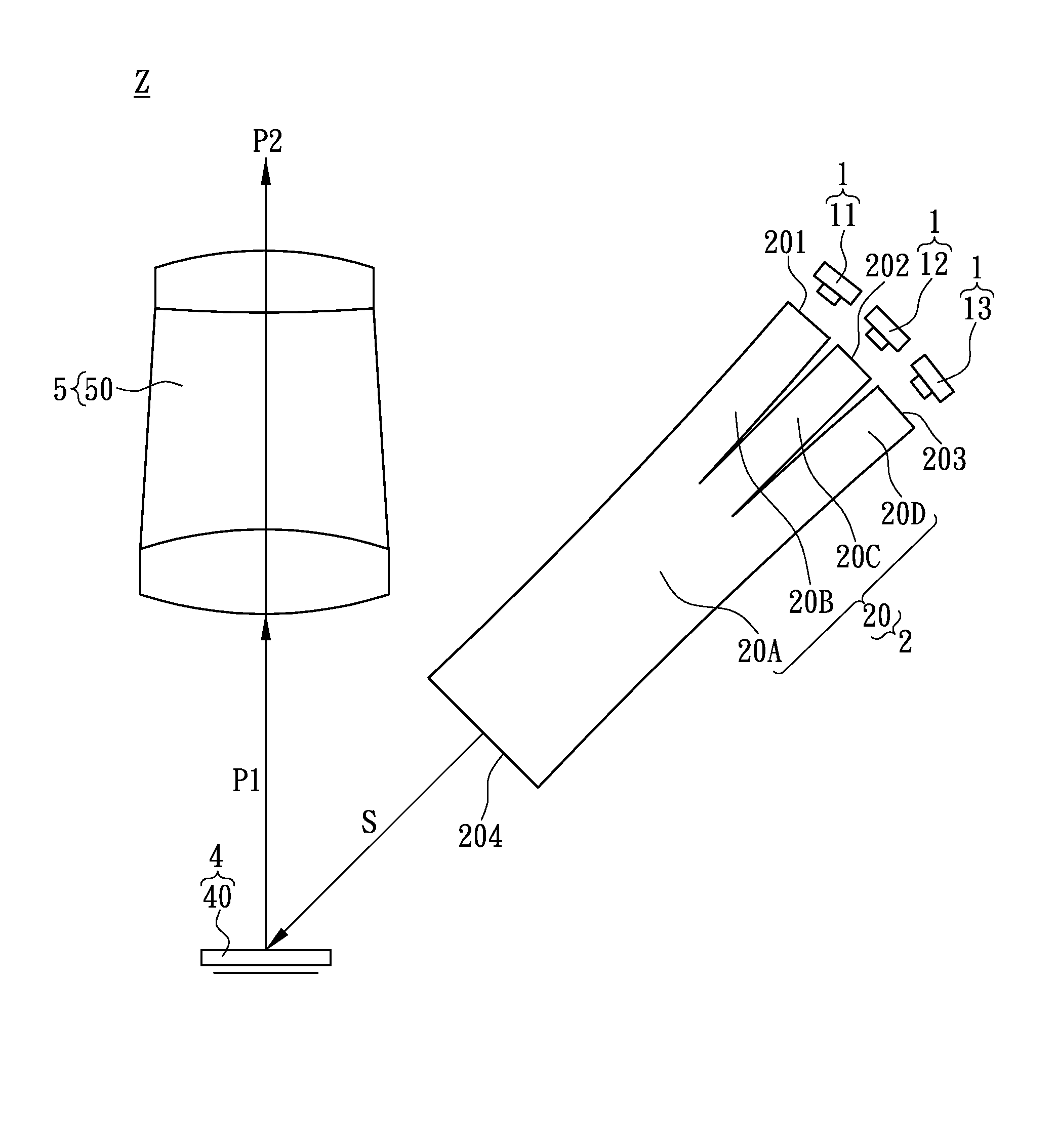
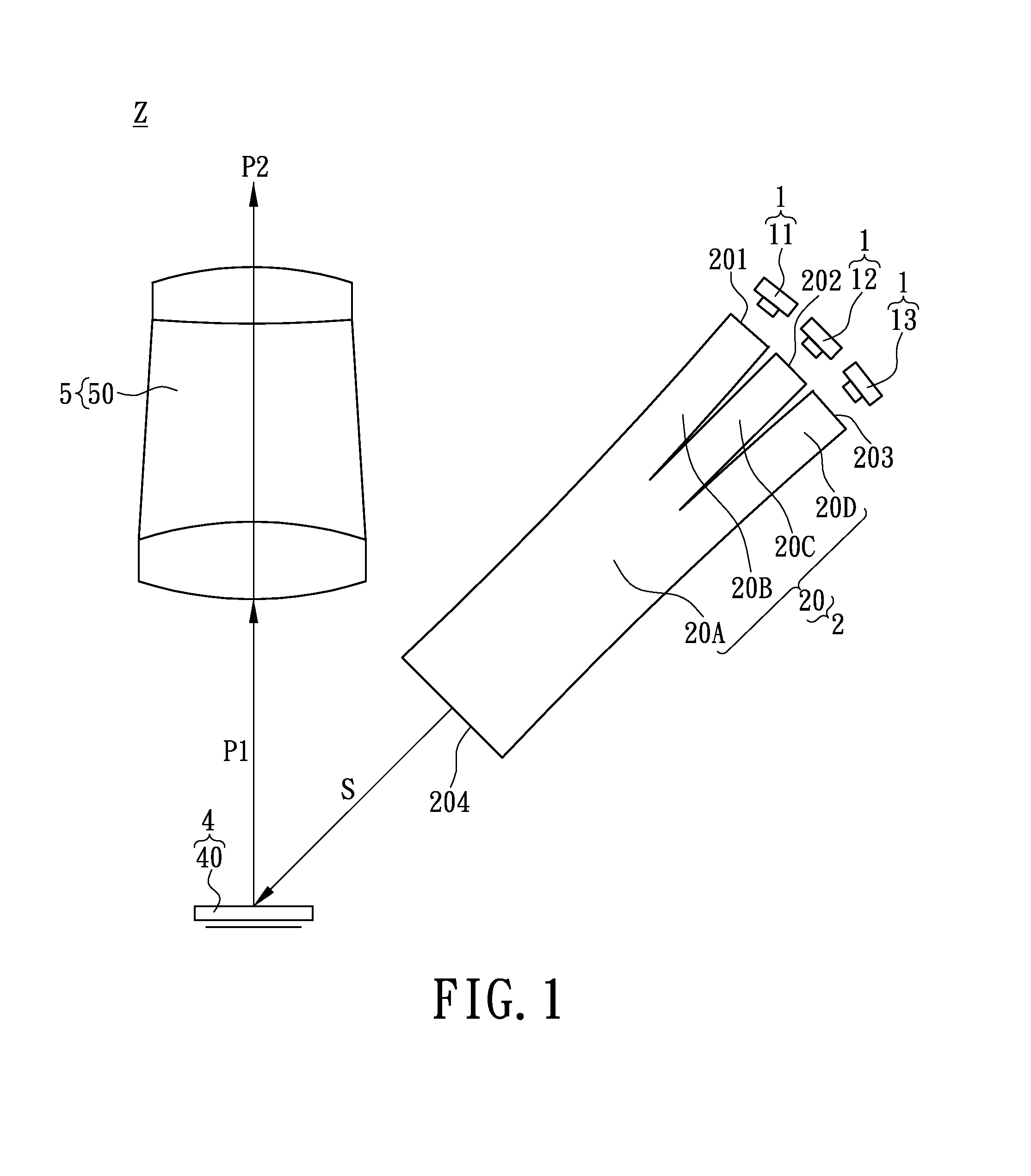
[0018]Referring to FIG. 1 to FIG. 4, where the first embodiment of the instant disclosure provides a projection device Z for increasing light-transmitting efficiency comprising: a light-emitting unit 1, a light-guiding unit 2, an image display unit 4 and an image projection unit 5, and the light-guiding unit 2 includes at least one photonic crystal fiber structure 20.

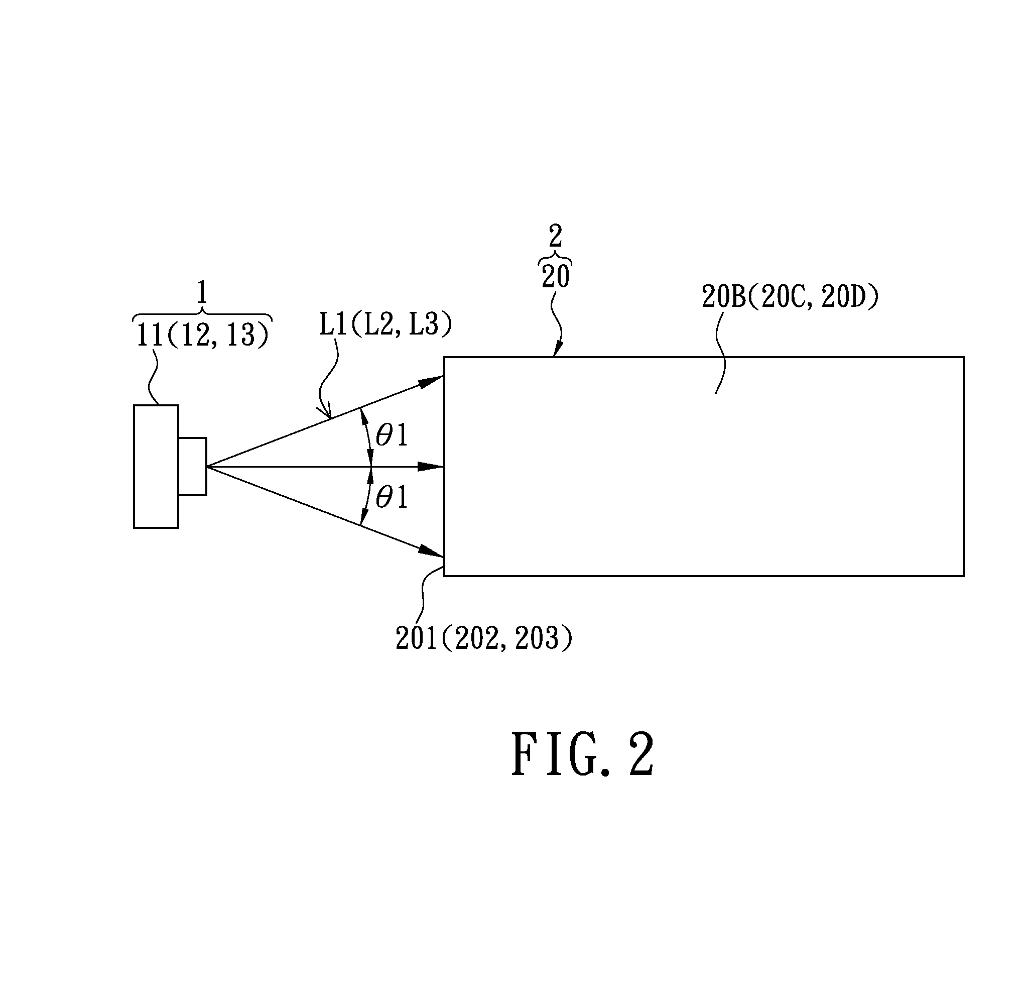
[0019]First, referring to FIG. 1 to FIG. 3, the light-emitting unit 1 includes a first light-emitting module 11 for generating a first predetermined light source L1, a second light-emitting module 12 for generating a second predetermined light source L2, and a third light-emitting module 13 for generating a third predetermined light source L3.

[0020]For example, referring to FIG. 1 and FIG. 2, the first light-emitting module 11 may be a red laser diode for generating a red light source, the second light-emitting module 12 may be a green laser diode for generating a green light source, and the third light-emitting module ...

second embodiment

[0028]Referring to FIG. 5, where the second embodiment of the instant disclosure provides a projection device Z for increasing light-transmitting efficiency comprising: a light-emitting unit 1, a light-guiding unit 2, a prism unit 3, an image display unit 4 and an image projection unit 5. Comparing FIG. 5 with FIG. 1, the difference between the second embodiment and the first embodiment is as follows: in the second embodiment, the prism unit 3 includes at least one polarization beam splitting prism 30 corresponding and adjacent to the light output terminal 204, the image display unit 4 includes at least one image display panel 40 corresponding and adjacent to one lateral side (such as a first lateral side 301) of the polarization beam splitting prism 30, and the image projection unit 5 includes at least one projection lens 50 corresponding and adjacent to another lateral side (such as a second lateral side 302 opposite to the first lateral side 301) of the polarization beam splittin...


PUM


Abstract

A projection device for increasing light-transmitting efficiency includes a light-emitting unit, a light-guiding unit, an image display module and an image projection unit. The light-emitting unit includes a first light-emitting module for generating a first predetermined light source, a second light-emitting module for generating a second predetermined light source, and a third light-emitting module for generating a third predetermined light source. The light-guiding unit includes at least one photonic crystal fiber structure having a first light input terminal for receiving the first predetermined light source, a second light input terminal for receiving the second predetermined light source, a third light input terminal for receiving the third predetermined light source, and a light output terminal. The image display module is corresponding and adjacent to the light output terminal. The image projection unit includes at least one projection lens corresponding and adjacent to the image display module.

Description

BACKGROUND OF THE INVENTION[0001]1. Field of the Invention[0002]The instant disclosure relates to a projection device, and more particularly to a projection device for increasing light-transmitting efficiency.[0003]2. Description of Related Art[0004]According to the advancement in optical and the projection display technology, digital projection devices with high pixel resolution are widely employed for briefings, meetings, conferences or trainings. They are also becoming popular for family entertainment. Potential consumers look for lightweight digital projection apparatuses with high image quality and brightness at reasonable prices.[0005]A projector is an apparatus that projects images onto an external screen by optical projection. A projector can be classified into four categories: CRT projector, liquid crystal display (LCD) projector, digital light processing (DLP) projector, and liquid crystal on silicon (LCOS) projector, basing on the type of light valve onboard. Moreover, th...

Claims


Application Information

Patent Timeline
Patent Type & Authority Applications(United States)
IPC IPC(8): G03B21/14
CPCG02B19/0028G02B19/0061G03B21/2013G03B21/2033G03B21/208G03B33/12
Inventor CHUNG, CHENG-JUNGHSU, SHENG-CHUNWANG, CHUN-HSIANGLIAO, LU-HSING
Owner AZUREWAVE TEHNOLOGIES INC
Learn More