
Communications terminal and method

a terminal and communication technology, applied in the field of communication terminals, can solve the problems of excessive signalling overhead associated with connection oriented signalling, which is required to establish user plane bearers and manage the core network tunnels during mobility, and achieve the effect of reducing the amount of signalling overhead, facilitating sms over lte, and avoiding the overhead associated with establishing user plane connections and their associated tunnels

Active Publication Date: 2014-05-22
CONVIDA WIRELESS LLC
View PDF23 Cites 7 Cited by
  • Summary
  • Abstract
  • Description
  • Claims
  • Application Information

AI Technical Summary

Benefits of technology

The present invention provides an efficient way of communicating small amounts of data without establishing a communications bearer between the communications terminal and the base station, reducing the amount of signalling overhead required. This can be done by utilizing the short message service (SMS) over the control plane, which avoids the need for user plane bearers and associated tunnels during mobility. The invention also enhances SMS utilizing network controlled handover based mobility management to further reduce the signalling overhead. Overall, the invention provides a cost-effective and efficient means for communicating small amounts of data.

Problems solved by technology

However, the overhead associated with connection oriented signalling which is required to establish user plane bearers and to manage the core network tunnels during mobility may be excessive when potentially only a few bytes of application data need to be transferred.

Method used


Image

  • Communications terminal and method
  • Communications terminal and method
  • Communications terminal and method

Examples


Embodiment Construction

[0033]The example embodiments will be generally described in the context of a 3GPP LTE architecture. However, the invention is not limited to an implementation in a 3GPP LTE architecture. Conversely, any suitable mobile architecture is considered to be relevant.

Conventional Network

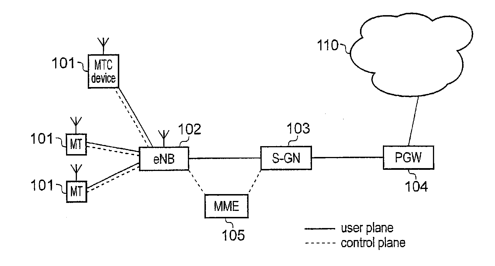
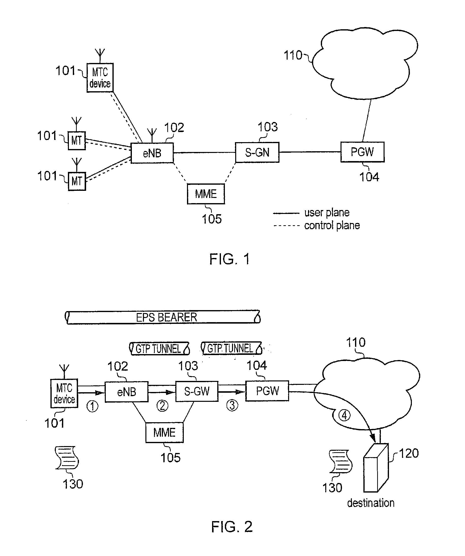
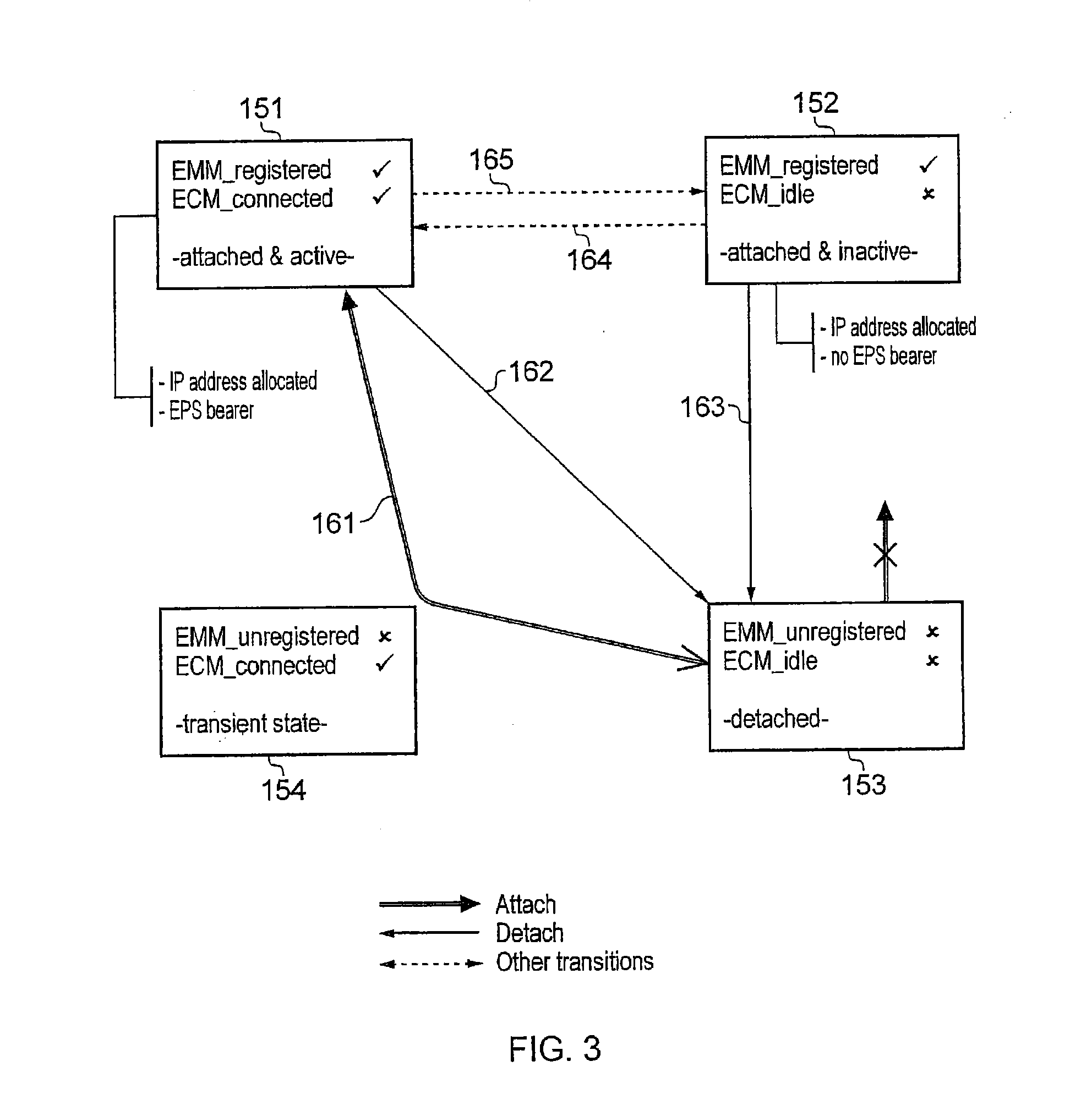
[0034]FIG. 1 provides a schematic diagram illustrating the basic functionality of a conventional mobile telecommunications network. The network includes one or more base stations 102 (one base station represented) connected to a serving gateway (S-GW) 103 for traffic in the user plane and to a Mobility Management Entity (MME) for signalling in the control plane. In LTE, the base stations are called e-NodeB, which are referred to in the following description as eNB. Each base station provides a coverage area 103 within which data can be communicated to and from mobile terminals 101. Data is transmitted from a base station 102 to a mobile terminal 101 within a coverage area via a radio downlink. Data is tran...


PUM


Abstract

A mobile communications network can establish one or more communications bearers for communicating data packets to / from a communications terminal via a radio network and a core network, each of the communications bearers established using context information associated with connections from the communications terminal to destination addresses, or to the communications terminal from source addresses. The communications terminal can, in an idle state, communicate a short signalling message data packet to a base station of the radio network, using predetermined parameters for configuring a mobile communications terminal transmitter, which correspond with parameters with which a receiver in the base station can receive the short message data packet, the short message data packet including an indication of context information usable by the mobile communications network for communicating the short message data packet to a mobility manager of the mobile communications network. The short message data packet can be context-less or quasi-context-less.

Description

FIELD OF THE INVENTION[0001]The present invention relates to communications terminals for communicating data packets to or from a mobile communications network via a radio access interface.BACKGROUND OF THE INVENTION[0002]Third and fourth generation mobile telecommunication systems, such as those based on the 3GPP defined UMTS and Long Term Evolution (LTE) architecture are able to support more sophisticated services than simple voice and messaging services offered by previous generations of mobile telecommunication systems.[0003]For example, with the improved radio interface and enhanced data rates provided by LTE systems, a user is able to enjoy high data rate applications such as mobile video streaming and mobile video conferencing that would previously only have been available via a fixed line data connection. The demand to deploy third and fourth generation networks is therefore strong and the coverage area of these networks, i.e. geographic locations where access to the network...

Claims


Application Information

Patent Timeline
Patent Type & Authority Applications(United States)
IPC IPC(8): H04L12/24H04W8/08H04W4/14H04L45/74H04W4/70
CPCH04W4/14H04W4/005H04W8/08H04L41/0806H04W4/70H04W88/08H04L45/74
Inventor BARRETT, STEPHEN, JOHN
Owner CONVIDA WIRELESS LLC
Learn More