Imaging system detector calibration

a detector calibration and imaging system technology, applied in the direction of material analysis using wave/particle radiation, instruments, tomography, etc., can solve the problems of over-noted conventional ct detectors not being optimal or even appropriate, and affecting the accuracy of calibration

Active Publication Date: 2014-05-22
KONINKLJIJKE PHILIPS NV
View PDF7 Cites 15 Cited by
  • Summary
  • Abstract
  • Description
  • Claims
  • Application Information

AI Technical Summary

Problems solved by technology

In some instances, the above-noted conventional CT detectors may not be the optimal choice or even appropriate, for example, for applications such as those involving spectral CT, photon counting, or protocols using very low detected x-ray flux.
Unfortunately, the above noted materials have unstable that the gains change more frequently over time, relative to the gain of the aforementio

Method used


Image

  • Imaging system detector calibration
  • Imaging system detector calibration
  • Imaging system detector calibration

Examples


Embodiment Construction

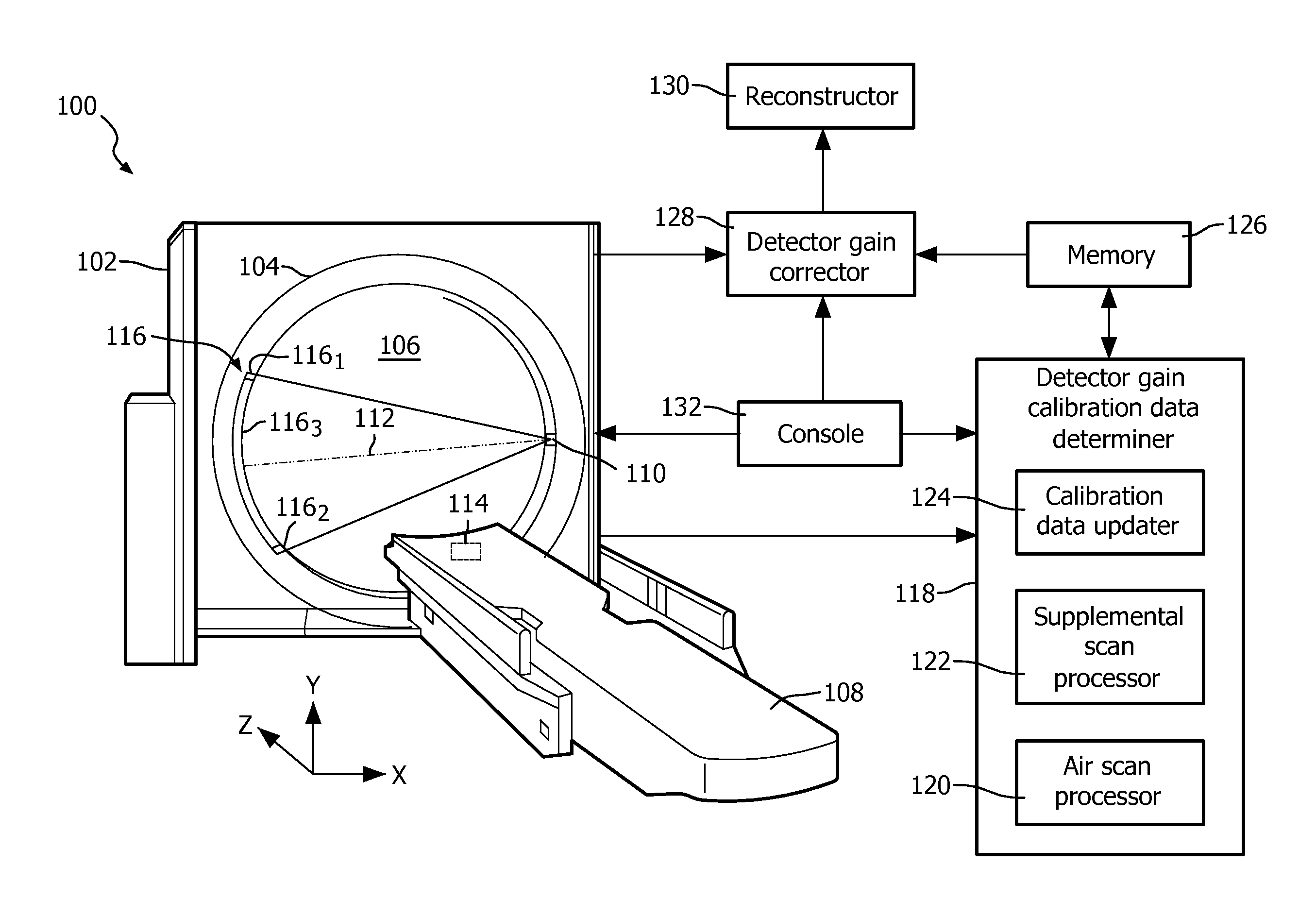
[0022]FIG. 1 illustrates an imaging system 100 such as a computed tomography (CT) scanner.

[0023]The imaging system 100 includes a stationary gantry 102 and a rotating gantry 104, which is rotatably supported by the stationary gantry 102. The rotating gantry 104 is configured to rotate around an examination region 106 about a longitudinal or z-axis.

[0024]A subject support 108, such as a couch, supports an object or subject (human or animal) in the examination region 106 and positions the object or subject with respect to x, y, and / or z axes before, during and / or after scanning.

[0025]A primary source 110, such as an x-ray tube, is supported by the rotating gantry 104 and rotates in coordination with the rotating gantry 104 about the examination region 106. The primary source 110 emits a generally fan, cone, or wedged shaped radiation beam that traverses along a path 112 from one side of the examination region 106 to the other. The primary source 110 is used to perform a conventional a...


PUM


Abstract

A system (100) includes a stationary gantry (102) and a rotating gantry (104), wherein the rotating gantry is rotatably supported by the stationary gantry. The rotating gantry (104) includes a primary source (110) that emits primary radiation and a detector array (116) having at least one row of detector elements (502) extending along a longitudinal axis. The primary source and the detector array are located opposite each other, across an examination region, and the primary radiation traverses a path (112) between the primary source and the detector array and through an examination region (106) and illuminates the at least one row of detector elements of the detector array, which detects the primary radiation. The system further includes a supplemental source (114), wherein the supplemental source is affixed to a non-rotating portion of the system and emits radiation that traverses a sub-portion of the path and illuminates the at least one row of detector elements of the detector array, which detects the secondary radiation.

Description

FIELD OF THE INVENTION[0001]The following generally relates to calibrating radiation sensitive detectors of an x-ray based imaging system detector array and is described with particular application to computed tomography (CT); however, the following is also amenable to other x-ray based imaging systems.BACKGROUND OF THE INVENTION[0002]A CT scanner generally includes an x-ray tube supported by a rotating gantry, which is rotatably affixed to a stationary gantry. The x-ray tube emits radiation that traverses an examination region and a portion of an object or subject therein. A subject support positions the object or subject in the examination region for scanning. A radiation sensitive detector array is disposed across the examination region, opposite the x-ray tube, and includes a plurality of detector elements that detects radiation traversing the examination region and produces projection data indicative of the detected radiation. The projection data can be reconstructed to generat...

Claims


Application Information

Patent Timeline
IPC IPC(8): G01T7/00G01N23/04
CPCG01N23/046G01T7/005A61B6/032A61B6/4007A61B6/4233A61B6/585G01T1/249
Inventor CARMI, RAZ
Owner KONINKLJIJKE PHILIPS NV
Why Eureka
Try Eureka