Selection of platelet rich plasma components via mineral binding

a technology of platelet rich plasma and mineral binding, which is applied in the field of medical devices with mineral coated substrates and autologous biological molecules, can solve the problems of limited bioavailability, limited bioavailability, and the need to deliver large doses of biological molecules, and achieve the effect of reducing the number of patients

Inactive Publication Date: 2014-05-22
WISCONSIN ALUMNI RES FOUND
View PDF5 Cites 0 Cited by
  • Summary
  • Abstract
  • Description
  • Claims
  • Application Information

AI Technical Summary

Benefits of technology

[0012]The coated devices and methods offer the possibility of selecting specific biological molecules from bodily fluids such as, for example, blood and blood-derived solutions that may be obtained intraoperatively. Moreover, because the biological molecules may be autologous biological molecules, the dosing and regulatory issues facing current biological molecules may be mitigated.

Problems solved by technology

Despite the clinical success of biologics, there are significant limitations related to their delivery.
For example, the materials that serve as carriers for biologics, such as collagen sponges, are often inappropriate for orthopedic applications because they do not seamlessly incorporate into standard clinical procedures, and thus, require adoption and training of the medical practitioner.
In addition, biologic molecules may quickly diffuse away from carrier materials and may rapidly degrade in vivo (e.g., t1 / 2 of BMP2˜minutes), which results in limited bioavailability and a need to deliver large doses of the biological molecules.
These large doses may be costly and may present a significant safety concern in the clinical orthopedics community, as they have led to edema and ectopic bone formation in multiple recent clinical studies.
Thus, there are significant challenges associated with developing biologics for clinical applications.
Clinical use of PRP has produced promising, but inconsistent results due to the broad variability in the production of PRP by various concentrating equipment and techniques, as well as individual variability in the platelet concentration of plasma.
The preparation and use of biologics, especially those such as blood and blood-derived products, may involve a cumbersome regulatory path.

Method used


Image

  • Selection of platelet rich plasma components via mineral binding
  • Selection of platelet rich plasma components via mineral binding
  • Selection of platelet rich plasma components via mineral binding

Examples


example 1

Mineralized Film and PRP

[0079]In this Example, the protein concentration of PRP was determined after incubation with a mineralized poly lactide glycolide (PLG) film.

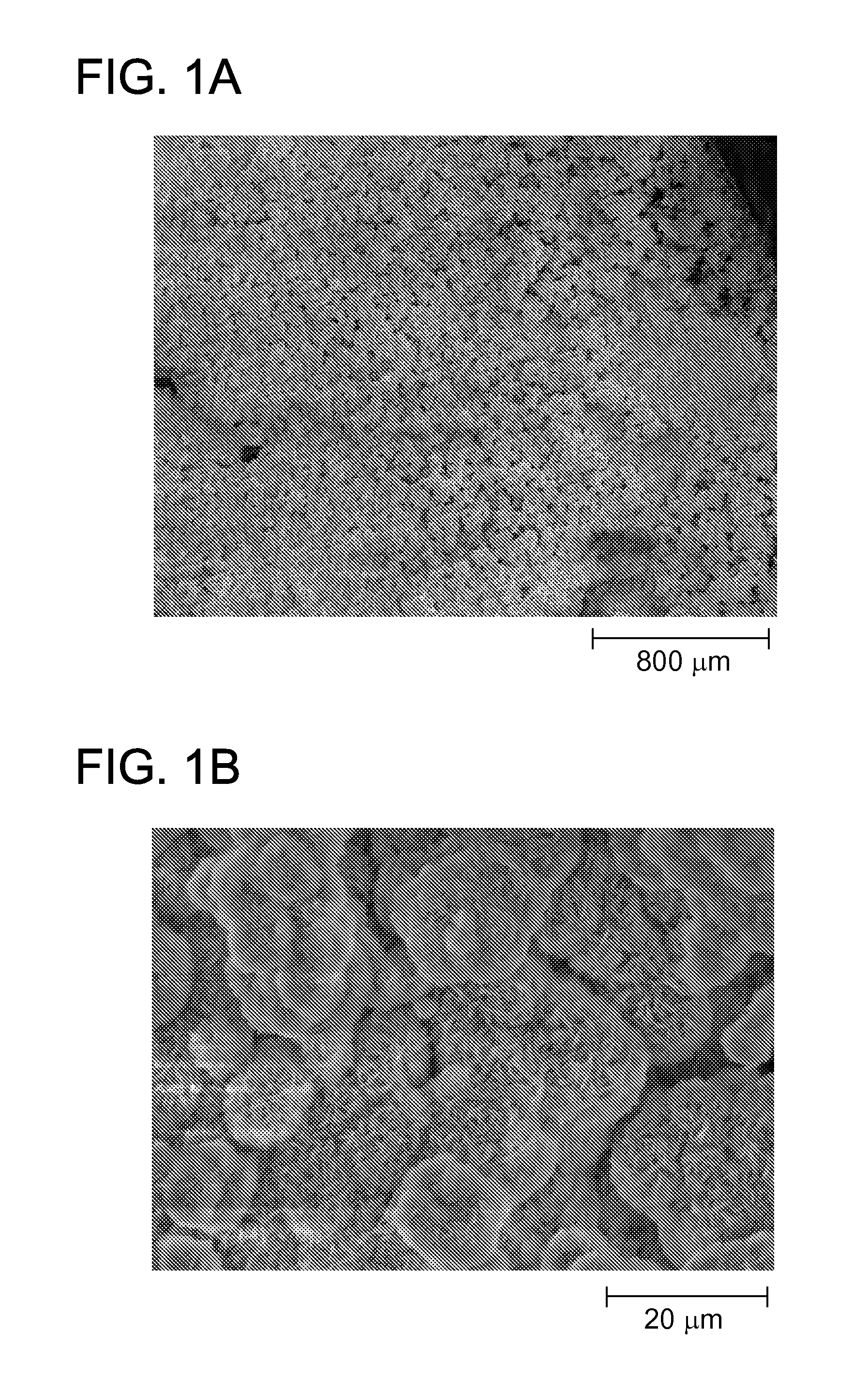
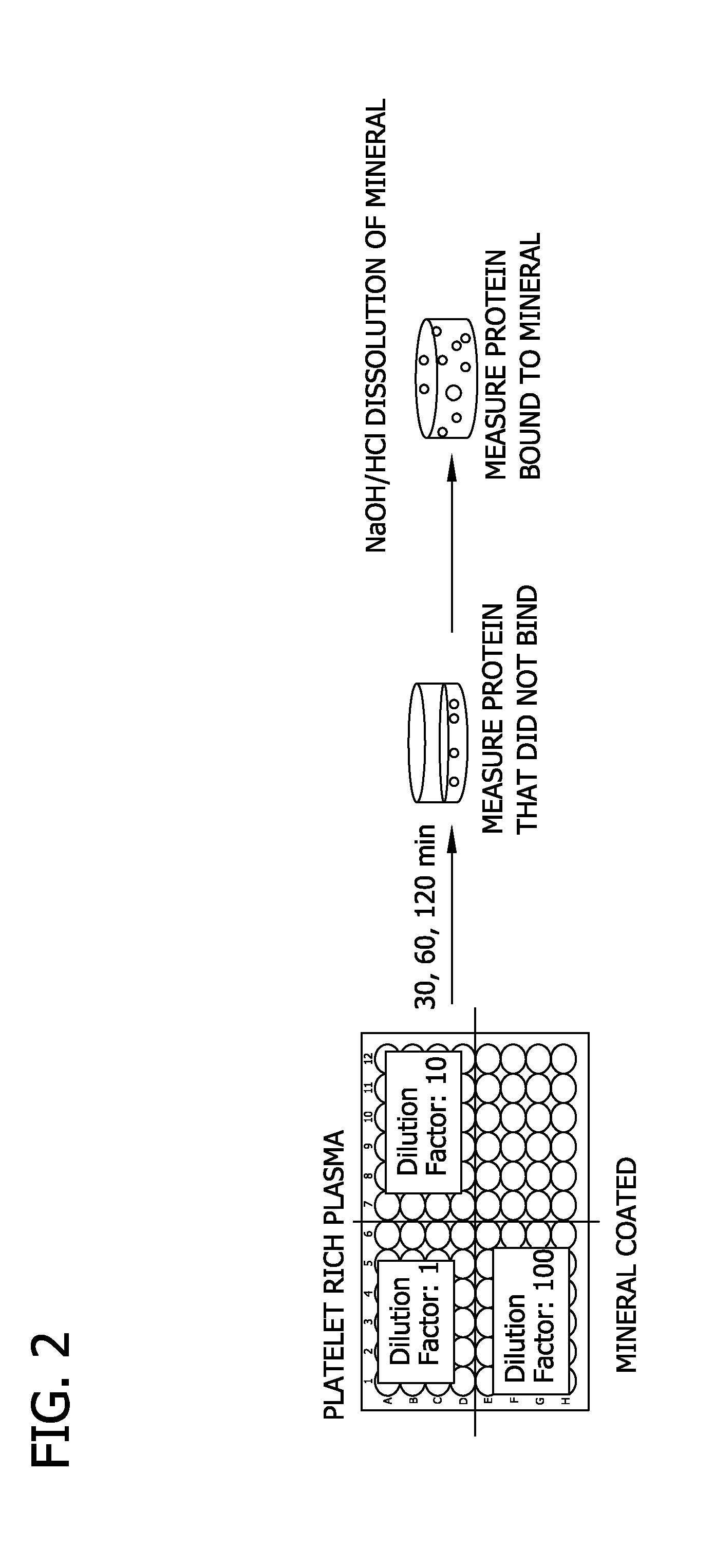
[0080]Specifically, poly lactide glycolide (85:15) was solvent casted into a film. The film was mineralized for 10 days using mSBF to form a mineralized coating on the PLG film (FIG. 1A and FIG. 1B). Blood was collected from sheep and centrifuged at 312×g and 1248×g to obtain PRP having a platelet count of 886 k / μl. PRP was subjected to cycles of freeze-thaw to lyse platelets. The resulting PRP was diluted by factors of 1, 10, and 100 in 0.001 M phosphate (PO4) buffer. The total protein concentration of each PRP dilution was determined by BCA assay.

[0081]As shown in FIG. 2, mineralized PLG films were incubated with each PRP dilution at 0 minute, 30 minute, 60 minute and 120 minute time points to allow proteins to bind to the mineralized PLG films. After incubation, the films were transferred to a new plate and rinsed wit...

example 2

Selective Elution of PRP Components

[0083]In this Example, elution of proteins from mineralized PLG wells with varying phosphate molarities was determined

[0084]Specifically, wells of a 96-well plate were coated with a mineralized film made as described above. PRP was obtained and subjected to cycles of freeze-thaw to lyse platelets as described above. As shown in FIG. 5, mineralized PLG wells were incubated for 1 hour to allow proteins to bind. Unbound proteins were rinsed off using water. Bound proteins were eluted from the mineralized PLG wells for 15 minute, 60 minute, and 90 minute time points using 0.001 M, 0.05 M, 0.11 M, 0.17 M, and 0.25 M PO4 (1st Protein Elution) and measured by BCA assay. Proteins that remained bound after the 1st Protein Elution were eluted from the mineralized PLG wells by incubating the mineralized PLG wells using 0.2 M NaOH. The 0.2 M NaOH eluate was neutralized using 0.2 M HCl in 0.01 M HEPES (2nd Protein Elution). The protein concentration of the 2nd ...

example 3

Selective Elution of PRP Components

[0088]In this Example, elution of proteins from mineralized PLG wells with varying phosphate molarities was determined

[0089]Specifically, PLG wells were mineralized as described above. PRP was obtained and subjected to cycles of freeze-thaw to lyse platelets as described above. As shown in FIG. 9, mineralized PLG wells were incubated for 1 hour to allow proteins to bind. Unbound proteins were rinsed off using water. Bound proteins were eluted from the mineralized PLG wells for less than 5 minutes (buffers were placed into the wells and immediately collected), 30 minutes and 90 minutes using water, 0.001 M, 0.05 M, 0.11 M, 0.17 M, and 0.25 M PO4 (1st Protein Elution; PO4 eluted) and measured using an AGILENT™ protein assay. Proteins that remained bound after the 1st Protein Elution (using phosphate buffer) were eluted a second time from the mineralized PLG wells by incubating the mineralized PLG wells using 0.2 M HCl / 0.01 M HEPES. The 0.2 M HCl / 0.01...


PUM

PropertyMeasurementUnit
pHaaaaaaaaaa
concentrationaaaaaaaaaa
supraphysiological concentrationsaaaaaaaaaa

Abstract

Mineral coated devices and methods for delivering an autologous biological molecule using the mineral coated devices are disclosed. The mineral coated devices allow for the isolation and delivery of a biological molecule obtained from the same subject to avoid the safety concerns of current biological therapies obtained by recombinant methods and purification from animal sources. Methods for selectively isolating and eluting a biological molecule using the mineral coated devices are also disclosed.

Description

STATEMENT OF GOVERNMENT SUPPORT[0001]This invention was made with government support under AR059916 and HL093282 awarded by the National Institutes of Health. The government has certain rights in the invention.BACKGROUND OF THE DISCLOSURE[0002]The present disclosure relates generally to medical devices. More particularly, the present disclosure relates to medical devices having a mineral coated substrate and an autologous biological molecule. The present disclosure further relates to methods for selectively isolating a biological molecule from a bodily fluid using the coated devices and methods for selectively eluting a biological molecule from the coated devices.[0003]The delivery of biological molecules (“biologics”) such as growth factors to promote musculoskeletal healing has become a popular approach in industry, with the market for orthopedic growth factors, for example, nearly quadrupling between 2003 and 2008. One delivery strategy involves embedding biologics within collage...

Claims


Application Information

Patent Timeline
Patent Type & Authority Applications(United States)
IPC IPC(8): A61K47/48
CPCA61K47/48992A61L17/005A61L17/12A61L17/145A61L27/18A61L27/306A61L27/32A61L27/3616A61L27/54A61L31/005A61L31/06A61L31/086A61L31/088A61L31/16A61L2300/252A61L2300/414A61K47/6957C08L67/04
Inventor MURPHY, WILLIAM L.VANDERBY, RAYBAER, GEOFFREYGRAF, BEN K.LEE, JAE SUNGCHAMBERLAIN, CONNIE
Owner WISCONSIN ALUMNI RES FOUND
Why Eureka
Try Eureka