Circuit board and method of mounting electronic component on circuit board

Inactive Publication Date: 2014-05-29
SAMSUNG DISPLAY CO LTD
View PDF5 Cites 4 Cited by
  • Summary
  • Abstract
  • Description
  • Claims
  • Application Information

AI Technical Summary

Benefits of technology

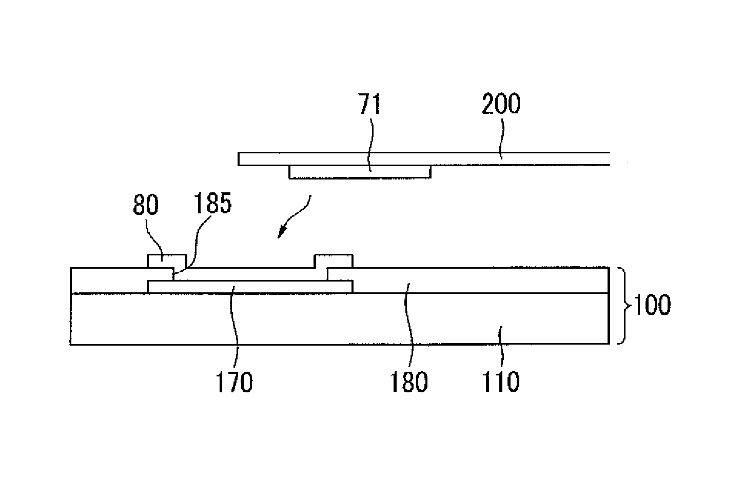
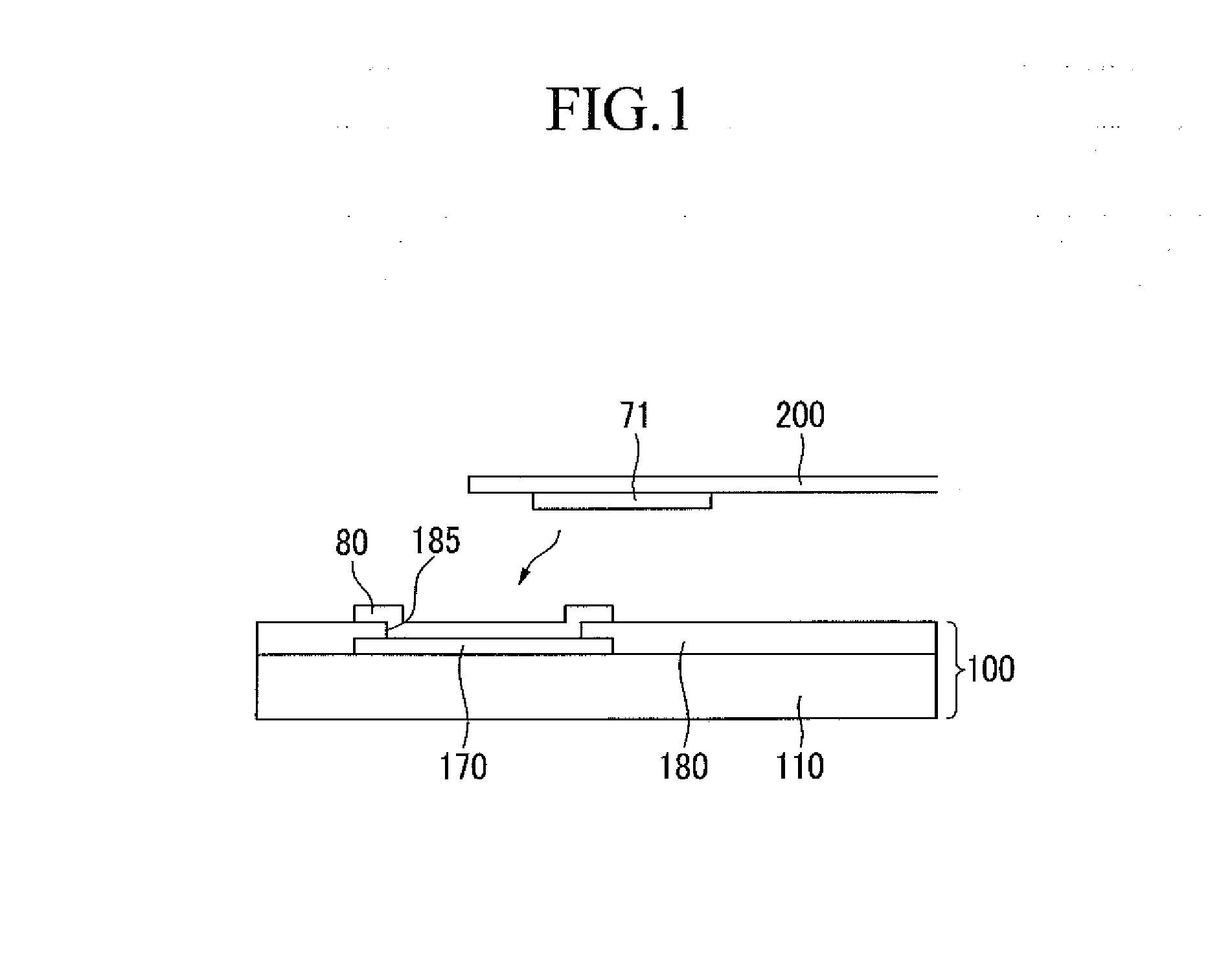
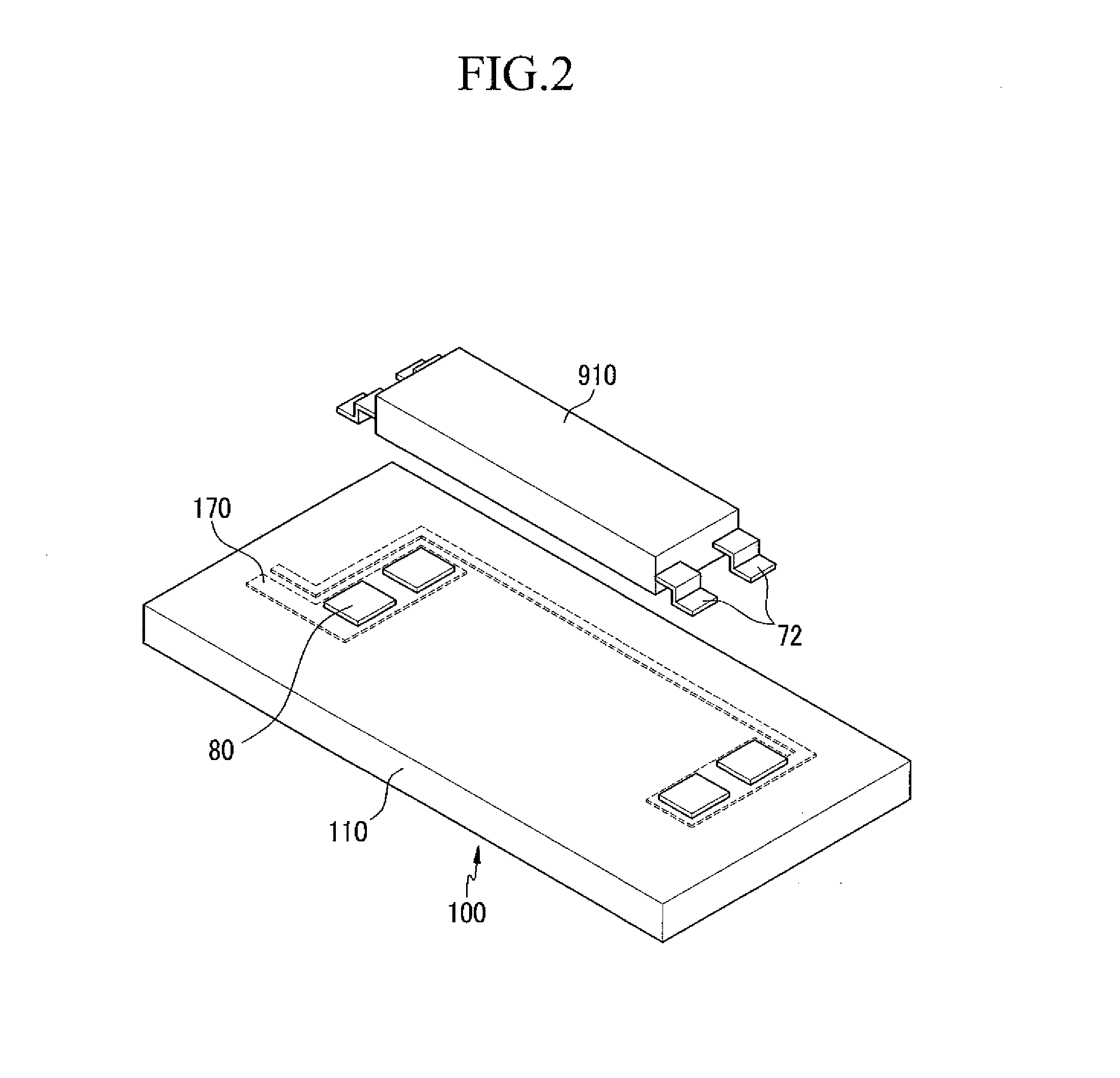
The present invention relates to a circuit board and a method for mounting electronic components on the circuit board. The invention provides a pad pattern that includes a basic pattern and one or more additional patterns. The basic pattern has a region where the connection terminal of an electronic component is attached by solder, while the one or more additional patterns have regions where the connection terminal is not attached. The circuit board also includes an exposed side or an exposed point capable of limiting the mounting position of the electronic component to prevent it from exceeding an alignment margin. This design prevents poor connection and increases reliability against tensional force. Additionally, the invention ensures that the electronic component is fixed in a normal direction without being inclined on the circuit board, thereby preventing misalignment-related defects.

Problems solved by technology

When the solder fillet is not properly formed, poor contact results between the mounted electronic component and the circuit board, so that the electronic component may be separated.
For example, in a case where the electronic component is an LED package, when the LED package is fixed at an incline, the LED package is misaligned with respect to another component, such as a light guide plate, so that luminance becomes non-uniform, thereby causing deterioration of a display quality.

Method used


Image

  • Circuit board and method of mounting electronic component on circuit board
  • Circuit board and method of mounting electronic component on circuit board
  • Circuit board and method of mounting electronic component on circuit board

Examples


Embodiment Construction

[0033]Exemplary embodiments of the present invention will be described more fully hereinafter with reference to the accompanying drawings. As those skilled in the art would realize, the described embodiments may be modified in various different ways, all without departing from the spirit or scope of the present invention.

[0034]In the drawings, the thickness of layers, films, panels, regions, etc., may be exaggerated for clarity. Like reference numerals may designate like elements throughout the specification. It will be understood that when an element such as a layer, film, region, or substrate is referred to as being “on” another element, it can be directly on the other element or intervening elements may also be present.

[0035]A circuit board according to an exemplary embodiment of the present invention will be described in detail below with reference to the drawings.

[0036]A circuit board according to an exemplary embodiment of the present invention will be described with reference...


PUM

PropertyMeasurementUnit
Lengthaaaaaaaaaa
Angleaaaaaaaaaa
Adhesion strengthaaaaaaaaaa

Abstract

Provided are a circuit board, and a method of mounting an electronic component on the circuit board. The circuit board according to an exemplary embodiment of the present invention includes: a pad pattern including a basic pattern and one or more additional patterns connected to the basic pattern, in which the basic pattern includes a region in which a connection terminal of an electronic component is attached by solder, the one or more additional patterns include regions in which the connection terminal of the electronic component is not attached, and the basic pattern includes an exposed side or an exposed point capable of limiting a mounting position so as to prevent the electronic component from exceeding an alignment margin.

Description

CROSS-REFERENCE TO RELATED APPLICATION[0001]This application claims priority to and the benefit of Korean Patent Application No. 10-2012-0137018 filed in the Korean Intellectual Property Office on Nov. 29, 2012, the entire contents of which are incorporated herein by reference.TECHNICAL FIELD[0002]The present invention relates to a circuit board, and more particularly, to a circuit board and a method of mounting an electronic element on the circuit board.DISCUSSION OF THE RELATED ART[0003]An electronic device, such as a display device, includes a plurality of electronic components, such as a transistor, a diode, s resistor, and an IC chip. In general, the electronic components may be mounted on various circuit boards, such as a printed circuit board, by methods such as soldering and the like. The printed circuit board is formed by printing a circuit pattern with a conductive material, such as copper, on an insulation substrate. The circuit pattern includes a connection pattern for c...

Claims


Application Information

Patent Timeline
IPC IPC(8): H05K1/18H05K13/04
CPCH05K13/0465H05K1/181H05K1/111H05K3/3421H05K2201/09381Y02P70/50H05K1/18H05K3/34H05K13/04
Inventor CHOI, CHUNG-WONLEE, SEOK HWANCHOI, MIN-SOO
Owner SAMSUNG DISPLAY CO LTD
Why Eureka
Try Eureka