Hydraulic Percussion Apparatus and Method of Use

Active Publication Date: 2014-05-29
KLX ENERGY SERVICES
View PDF5 Cites 26 Cited by
  • Summary
  • Abstract
  • Description
  • Claims
  • Application Information

AI Technical Summary

Benefits of technology

[0021]These repeated percussions can be utilized to aid in the drilling of formation, cement, plugs, scale, rock, or the like in a wellbore or pipe. These repeated percussions can also be utilized in fishing operations to introduce vibrations in an attempt to free stuck objects in a wellbore. These repeated percussions may further b

Problems solved by technology

The hard and brittle formations that are frequently encountered can be difficult to drill by merely rotating a drill bit.
The rotation of the drill bit alone is ineffective as the rotation will cause the bit to simply heat up and become dull rather than advance the hole.
This process is very time consuming, therefore is not an adequate or economical solution.
Such turbine technology is very complex and the percussive devices that rely on such technology are expensive and complicated to manu

Method used


Image

  • Hydraulic Percussion Apparatus and Method of Use
  • Hydraulic Percussion Apparatus and Method of Use
  • Hydraulic Percussion Apparatus and Method of Use

Examples


second embodiment

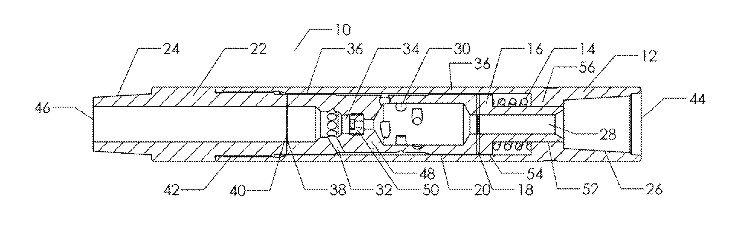
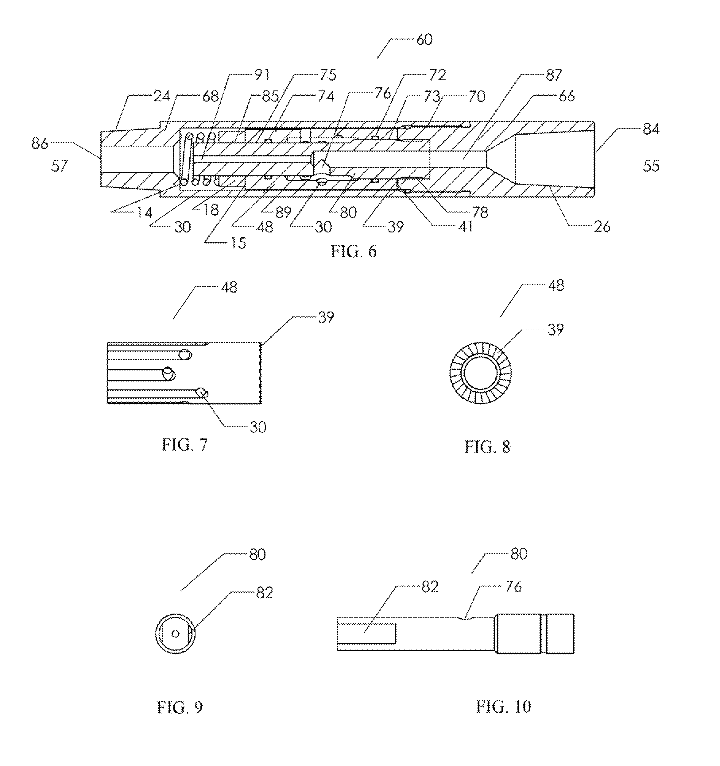
[0048]FIG. 6 shows the hydraulic percussive apparatus (60) of the present invention utilized to provide upward percussive or hammering forces to a pipe string having a central bore through which fluid may be introduced. The apparatus (60) has an upper end (55) and a lower end (57) and is configured for threadable attachment to the pipe string when deployed in a wellbore.

[0049]Apparatus (60) is comprised of a top sub (66) and a tubular housing (68) that is threaded on its radial surfaces where it may be threadedly attached to a tubular housing (68) by means of threaded connection (70). Positioned within the housing (68) is a rotatably mounted longitudinally extending rotor (48), a thrust bearing (18), a mandrel (80), and a spring (14). Housing (68) and rotor (48) are illustrated as a single components but may consist of a multitude of individual parts connected together possibly by one or more of several means such as threaded connections, splines, keyways, welding, brazing, press or...

first embodiment

[0053]Profiled surfaces (39) and (41) may have the same configuration as profiled surfaces (38) and (39) of the The features of profiled surfaces (38), (39), (40), and (41) are shown as having saw-tooth profiles but these profiled surface features may be of any suitable form such as waveform, sinusoidal, or other irregular profiled surface. The features of profiled surfaces (38), (39), (40), and (41) are also shown to be of the same size and shape, and are uniform around the entire area circumference of the interfacing profiled surfaces but the features of the profiled surfaces (38), (39), (40), and (41) may be non-uniform and of differing size and shape.

[0054]The thrust bearing (18) is positioned within the housing (68) between spring (14) and the rotor (48) and is shown as a thrust sleeve for simplicity and clarity of illustration but the thrust bearing (18) can be of many forms such as those mentioned when discussing the thrust bearing of the embodiment shown in FIG. 1. Thrust b...


PUM


Abstract

A hydraulic percussive apparatus is disclosed for generating vibrating forces to a pipe string. The apparatus is attached to the pipe string a central bore through which fluid may be introduced into the apparatus. The apparatus has a tubular housing, an anvil surface with an irregularly profiled surface, and a rotor with an irregularly profiled hammer surface that is urged to move axially toward and away from the anvil surface. The rotor has a longitudinally extending fluid bore and a tangentially oriented fluid port in communication with the longitudinal fluid bore of the rotor. Fluid entering the rotor's fluid bore and exiting the rotor's tangentially oriented fluid port rotates the rotor, and thus the irregularly profiled hammer surface on the irregularly profiled anvil surface, moving the hammer surface toward and away from the anvil producing intermittent impact forces.

Description

PRIORITY[0001]This application claims priority to U.S. provisional application Ser. No. 61 / 728,422 filed Nov. 20, 2012 for Hydraulic Percussion Apparatus and Method of Use, the entire content of which is hereby incorporated by reference.FIELD OF THE INVENTION[0002]This invention pertains to downhole equipment for oil and gas wells. More particularly, it pertains to a hydraulic percussive apparatus for use on a wellbore pipe string such as a drillstring or coiled tubing string and, more particularly, this invention relates to an apparatus for imparting repeated percussions or impacts to the pipe string.BACKGROUND OF THE INVENTION[0003]A variety of geologic formations are often encountered as a wellbore is progressed during the drilling of an oil and gas well. Often these formations are comprised of very hard and sometimes brittle material such as rock, stone or shale. A rotating drill bit is placed at the end of a pipe string and is used to advance the wellbore through the various ge...

Claims


Application Information

Patent Timeline
IPC IPC(8): E21B1/02E21B7/24
CPCE21B4/14E21B7/24E21B4/06
Inventor BAUDOIN, TOBY SCOTT
Owner KLX ENERGY SERVICES
Why Eureka
Try Eureka