Method and a rotary wing aircraft having three engines

a technology of rotary wing aircraft and engine, which is applied in the direction of rotorcraft, transportation and packaging, depending on the number of power plants, etc., can solve the problems of limited power that can be delivered by an engine, the power of the engine that was available, and the industrialization of any three-engined helicopter architectur

Active Publication Date: 2014-05-29
EUROCOPTER
View PDF2 Cites 42 Cited by
  • Summary
  • Abstract
  • Description
  • Claims
  • Application Information

AI Technical Summary

Benefits of technology

[0161]in flight, when the aircraft is flying at a forward speed slower than a threshold speed and when the speed of rotation of the rotary wing is less than a threshold speed of rotation and / or when the power needed for driving the rotary wing is greater than the available power delivered by the secondary engine, the secondary engine is no longer inhibited.

Problems solved by technology

By construction, the level of power that can be delivered by an engine is limited.
Under such circumstances, when the power from a single engine is found to be insufficient, manufacturers naturally arrange a plurality of engines on an aircraft.
For example, three-engined aircraft appeared in the 1960s because of the lack of power of the engines that were available at that time on aircraft presenting heavy weight.
Nevertheless, it is always possible to install engines having unequal maximum powers in order to satisfy safety requirements or in order to mitigate the lack of power of engines available on the market.
Nevertheless, the technical challenges that need to be solved have prevented industrialization of any three-engined helicopter architecture that has for example one engine of maximum power different from the maximum power of the others.
Dimensioning for such excess power levels is very penalizing and incompatible with optimizing an engine in terms of its weight, its cost, its fuel consumption, and its emissions (noise, CO2, .
It is also very complicated for such engines to be certified since they require additional testing such as specific endurance or “over-temperature” tests.
As a result, the control units act for example to limit the performance of engines in order to avoid overspeed of the rotary wing.
Under such circumstances, integrating three engines may involve control units of considerable size and weight.
In addition, the control systems of an aircraft and its engines may excite resonant modes of vibration in a rotary wing aircraft.
The complexity of developing torsional stability in the power drive train of the aircraft increases with the number of elements that contribute to the overall drive train, and thus with the number of engines installed.
A good compromise between the reactivity of an engine in response to a command for the pilot and the stability of the aircraft also constitutes a major challenge to overcome.
If the engines are very reactive, a rapid command from a pilot runs the risk of exciting a resonant mode of vibration of the aircraft.
Given that developing a twin-engined aircraft is difficult, it can be understood that developing an aircraft having three reactive engines is even more difficult.
Nevertheless, installing engines having unequal maximum powers involves major technical challenges.
Under such circumstances, such a solution would appear to be difficult to implement on a three-engined aircraft.
In particular, the reactivity of such an aircraft can be difficult to optimize.
However, if the engines have unequal maximum powers, the loss of the higher power engine needs to be compensated as quickly as possible by the lower power engine.
Furthermore, it can be difficult to control the aircraft under such conditions.
If the engines have unequal maximum powers, new control logic without power balance would appear to be difficult to develop for the purpose of managing the overall power to be delivered (i.e. the power available from each of the engines, its limits, the power required, etc.).
Furthermore, with engines that do not present identical maximum powers, their speeds of rotation may also be different, and that constitutes another difficulty.
Such power management may be even more complex if it is decided to stop one engine in order to improve fuel consumption.
The stability of the aircraft is even more problematic in the presence of three engines of unequal maximum power.
Consequently, unequal engines can be subjected to asymmetrical accelerations giving rise to false alarms concerning transient faults.
The torsional stability of the power transmission drive train of the aircraft can also represent a problem that is difficult to overcome.
Furthermore, it can be difficult to monitor the engines, since unequal engines are difficult to compare with one another.
This might result in difficulties in harmonizing the interfaces between the engines, or between the engines and the remainder of the aircraft.
However, implementing three engines that are identical can lead to difficulties in dimensioning the engines and their control units, and also to problems of stability.
Implementing unequal engines appears to be even more difficult, since it gives rise to problems of reactivity, control, stability, monitoring, or indeed integration.
Whatever the variant, making a three-engined aircraft thus gives rise to a variety of difficulties.
These difficulties make provision of a three-engined aircraft non-obvious, since a three-engined aircraft is not merely a twin-engined aircraft provided with a third engine.

Method used


Image

  • Method and a rotary wing aircraft having three engines
  • Method and a rotary wing aircraft having three engines
  • Method and a rotary wing aircraft having three engines

Examples


first embodiment

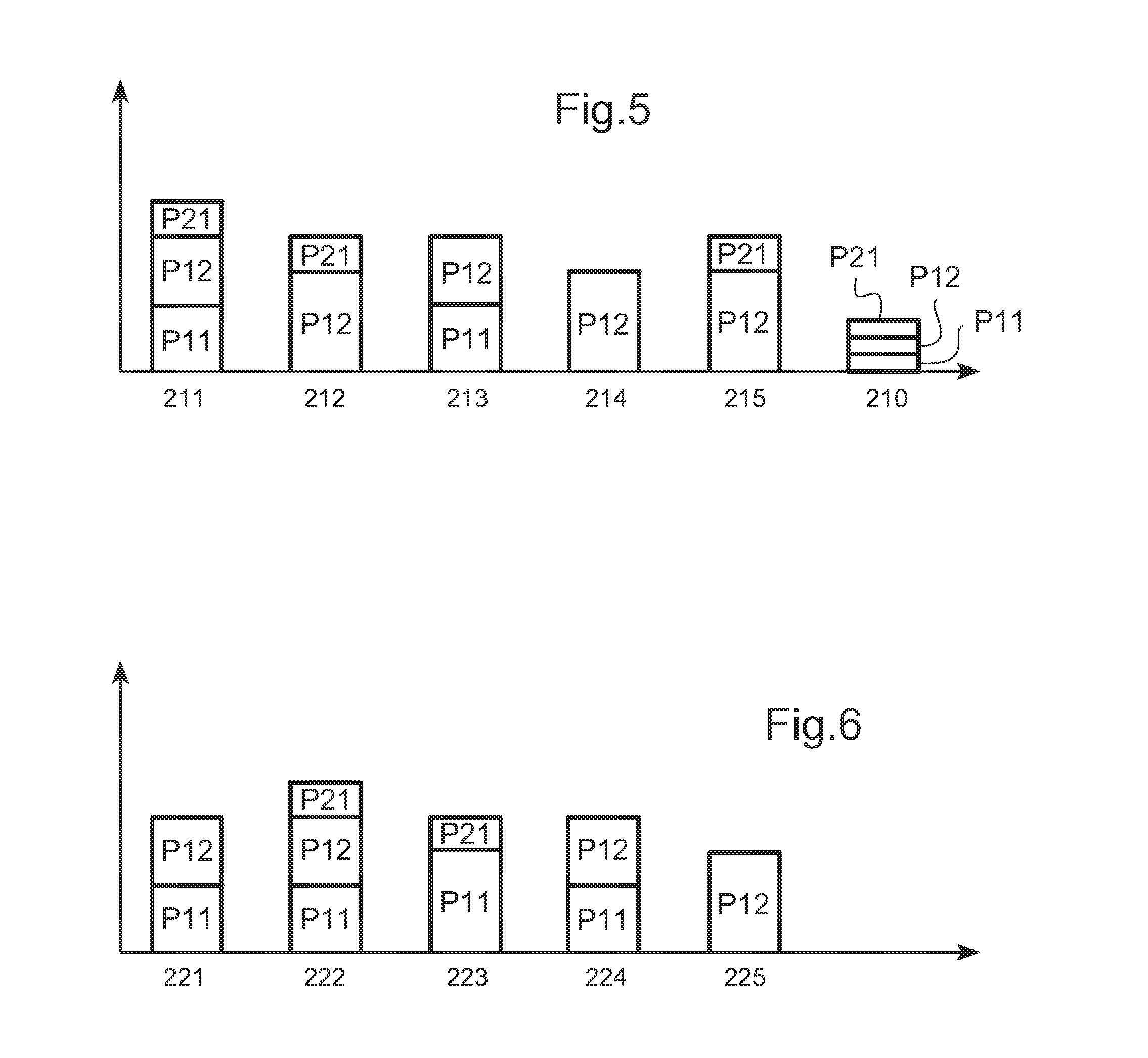
[0201]In the first embodiment, the secondary engine 21 is dimensioned so as to develop low maximum power. This maximum power is said to be “low” insofar as this maximum power is not sufficient to lead to overspeed of the rotary wing 2 when the main engines are stopped or idling.

[0202]Under such circumstances, the secondary engine may be started on the ground without any risk of leading to overspeed of the rotary wing.

[0203]In a first situation 210, the secondary engine 21 and the main engines 11 and 12 are caused to operate on the ground in order to drive the rotary wing 2. Since the main engines are regulated in application of a setpoint that is variable, the main regulation system must guarantee that the main and secondary engines will not generate overspeed of the rotary wing.

[0204]It is possible for the main engines to develop zero power on the ground.

[0205]The secondary engine optionally has a specific free turbine mode of regulation on the ground that is dedicated to generatin...

second embodiment

[0216]In a second embodiment, the secondary engine 21 is dimensioned so as to develop high maximum power. This maximum power is said to be “high” insofar as this maximum power is sufficient to give rise to overspeed of the rotary wing 2 when the main engines are stopped or idling.

[0217]Under such circumstances, the main engines are operated on the ground to drive the rotary wing and the secondary engine is inhibited so long as the aircraft is flying at an altitude below a threshold altitude or whenever the rotary wing exceeds a threshold speed of rotation.

[0218]When the aircraft is flying at a forward slower than a threshold speed and at an altitude higher than a threshold altitude, the secondary engine is no longer inhibited.

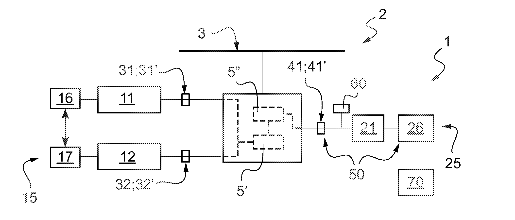
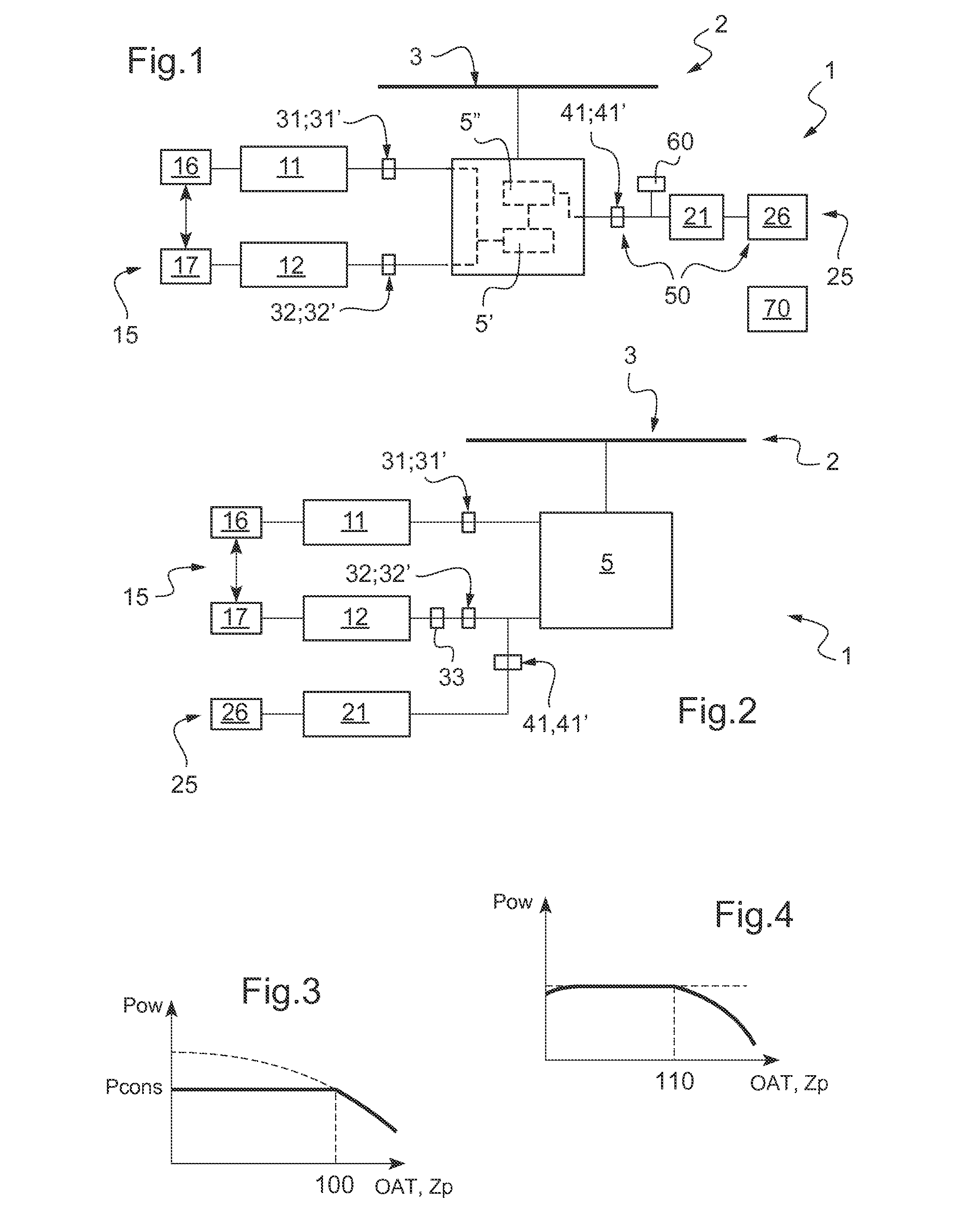
[0219]With reference to FIG. 1, the aircraft 1 has detection means 70 for detecting whether the aircraft is standing on the ground. By way of example, the detection means 70 comprise a radioaltimeter or a sensor arranged on landing gear.

[0220]The aircraft 1 is ...


PUM


Abstract

An aircraft (1) having a rotary wing (2) and at least one main gearbox (5) for driving rotation of said rotary wing (2), said aircraft (1) having a first main engine (11) and a second main engine (12) driving said main gearbox (5), said aircraft (1) being provided with a main regulation system (15) regulating the first main engine (11) and the second main engine (12) in application of a setpoint that is variable. A secondary engine (21) is also capable of driving said main gearbox (5), said aircraft (1) having a secondary regulation system (25) that regulates the secondary engine (21) in application of a setpoint that is constant and that is independent of said main regulation system (15).

Description

CROSS REFERENCE TO RELATED APPLICATION[0001]This application claims priority to French patent application No. FR 12 03181 filed on Nov. 26, 2012, the disclosure of which is incorporated in its entirety by reference herein.BACKGROUND OF THE INVENTION[0002](1) Field of the Invention[0003]The present invention relates to a rotary wing aircraft having three engines, and to a method of controlling the aircraft.[0004]It should be observed that the term “engine” is used to mean a power unit contributing to providing the aircraft with propulsion and / or lift. For a rotary wing aircraft, the term “engine” is used to designate a power unit that drives rotation of a main gearbox that in turn drives rotation of at least one rotor of the rotary wing.[0005](2) Description of Related Art[0006]An aircraft is sometimes fitted with an auxiliary power unit (APU). Such an auxiliary power unit may be used for example to generate electricity, to drive hydraulic systems, or indeed to contribute to starting...

Claims


Application Information

Patent Timeline
Patent Type & Authority Applications(United States)
IPC IPC(8): B64D31/00B64C27/12
CPCB64D31/06B64C27/12B64C27/14B64D31/00B64D35/08
Inventor GOMEZ, NAYIBE
Owner EUROCOPTER
Why Eureka
Try Eureka