RF induction lamp with reduced electromagnetic interference

a technology of electromagnetic interference and induction lamp, which is applied in the direction of transit tube circuit elements, cathode-ray/electron beam tube circuit elements, structural circuit elements, etc., can solve the problems of emi compliance, limited emi, and inflicted by any industrial and consumer product utilizing rf power, so as to reduce the conductive electromagnetic interference (emi) level. , the effect of simple and low cos

Inactive Publication Date: 2014-05-29
LUCIDITY LIGHTS
View PDF7 Cites 22 Cited by
  • Summary
  • Abstract
  • Description
  • Claims
  • Application Information

AI Technical Summary

Benefits of technology

[0017]The exemplary embodiments that follow provide an RF induction lamp with simple and low cost means for suppressing electromagnetic interference. This goal may be achieved by a bifilar winding of the lamp coupler having unequal winding wire lengths and by effective grounding of the

Problems solved by technology

The issue of electromagnetic interference (EMI) inflicted by any industrial and consumer product utilizing RF power is the subject of strict domestic and international regulations.
The permitted EMI level for consumer lighting devices is relaxed at frequencies around 2.65 MHz, but the increase in allowable EMI is limited and EMI still has to be addressed to comply with the regulations.
The EMI compliance is especially problematic for integrated, self-ballasted compact RF lamps.
Although this technique for reduction of conductive EMI has

Method used


Image

  • RF induction lamp with reduced electromagnetic interference
  • RF induction lamp with reduced electromagnetic interference
  • RF induction lamp with reduced electromagnetic interference

Examples


Embodiment Construction

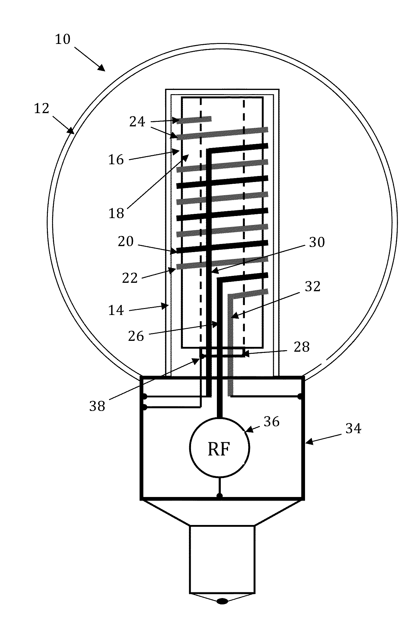
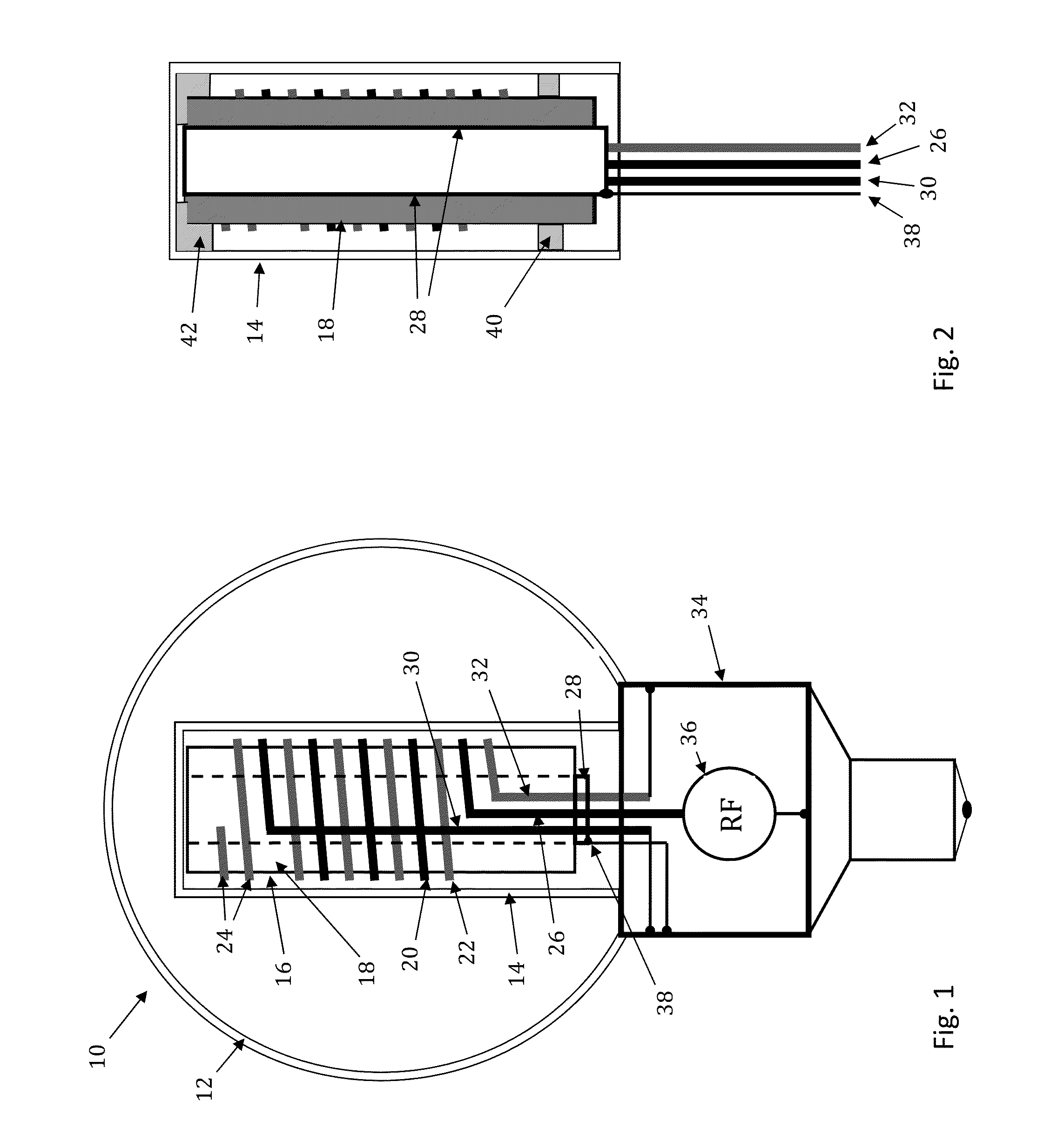
[0032]FIG. 1 illustrates a cross-section view of an inductive RF lamp in accordance with an exemplary and non-limiting embodiment. The RF lamp 10 comprises of a glass envelope 12 with a glass re-entrant cavity 14 sealed into the envelope 12 and forming a gas discharge vessel (burner) between them. The lamp burner is filled with a working gas mixture of a noble gas such as Argon, Krypton or others and Mercury vapor. The inner surface of burner, both the envelope 12 and the re-entrant cavity 14, are covered with a phosphor. With plasma discharge maintained in the burner, the UV radiation from plasma excites the phosphor, which converts UV light to visible light.

[0033]The plasma within the burner is maintained by the electromagnetic induction created by the RF lamp coupler 16 sitting inside the re-entrant cavity 14. The coupler 16 is energized by an RF power source (RF ballast) 36 placed in the ballast cap 34 and electrically connected to the local ground (buss), where the ballast cap ...


PUM


Abstract

An induction RF fluorescent lamp configuration providing reduced EMI includes a lamp envelope with a re-entrant cavity both covered on a partial vacuum side with phosphor and filled with a working gas mixture, a tubular ferromagnetic core on the non-vacuum side said re-entrant cavity wound directly on the said core with two windings having different numbers of turns, a first active winding having one end connected to an RF ballast and the other end connected to local ground, and a second passive winding having one end grounded and the other end free.

Description

BACKGROUND[0001]1. Field[0002]This invention relates to RF induction light sources, and more particularly to the suppression of electromagnetic interference in RF induction light sources.[0003]2. Description of Related Art[0004]The issue of electromagnetic interference (EMI) inflicted by any industrial and consumer product utilizing RF power is the subject of strict domestic and international regulations. According to these regulations, the EMI level emanating from RF light sources must not exceed some threshold value that may interfere with operation surrounding electronic devices, communication, remote control gadgets, medical equipment and life supporting electronics. The permitted EMI level for consumer lighting devices is relaxed at frequencies around 2.65 MHz, but the increase in allowable EMI is limited and EMI still has to be addressed to comply with the regulations.[0005]The conductive EMI of an RF light source (also referred herein as an RF lamp or lamp) is originated by t...

Claims


Application Information

Patent Timeline
IPC IPC(8): H01J65/04
CPCH01J65/048
Inventor GODYAK, VALERY A.MAYA, JAKOBLESTER, JAMES N.
Owner LUCIDITY LIGHTS
Why Eureka
Try Eureka