Antenna device and wireless communication device

a wireless communication and antenna device technology, applied in the direction of antennas, antenna details, semiconductor devices, etc., can solve the problems of difficult to secure a large communication range, complex configuration of antenna devices, and high manufacturing costs, so as to facilitate assembly, reduce the effect of mutual interference, and reduce the cost of manufacturing

Active Publication Date: 2014-05-29
MURATA MFG CO LTD
View PDF3 Cites 48 Cited by
  • Summary
  • Abstract
  • Description
  • Claims
  • Application Information

AI Technical Summary

Benefits of technology

[0034]According to this configuration, although a small-sized power supply coil is preferably used, an antenna device with high radiation efficiency is obtained. In addition, a power supply coil, the first coil antenna, and the second coil antenna can be disposed at appropriate positions, and this facilitates assembling. Furthermore, a power supply circuit can be protected against a surge caused by static electricity or thunder.
[0035]According to various preferred embodiments of the present invention, a first coil antenna substantially does not pick up an induction field of a second coil antenna, and also the second coil antenna substantially does not pick up an induction field of the first coil antenna. In

Problems solved by technology

According to the antenna devices disclosed in Japanese Unexamined Patent Application Publication No. 2004-213582 and Japanese Unexamined Patent Application Publication No. 2006-126901, although mutual interference between antennas that are adjacent to each other can be suppressed, loss (eddy-current loss) due to a conductive member and a soft magnetic member is likely to be large, and thus, it is difficult to secure a large communication range.
In addition, since the configuration of a tag becomes complicated, and also the size of the tag becomes large, manufacturing tolerance is large, and the manufacturing costs are likely to be hig

Method used


Image

  • Antenna device and wireless communication device
  • Antenna device and wireless communication device
  • Antenna device and wireless communication device

Examples


first preferred embodiment

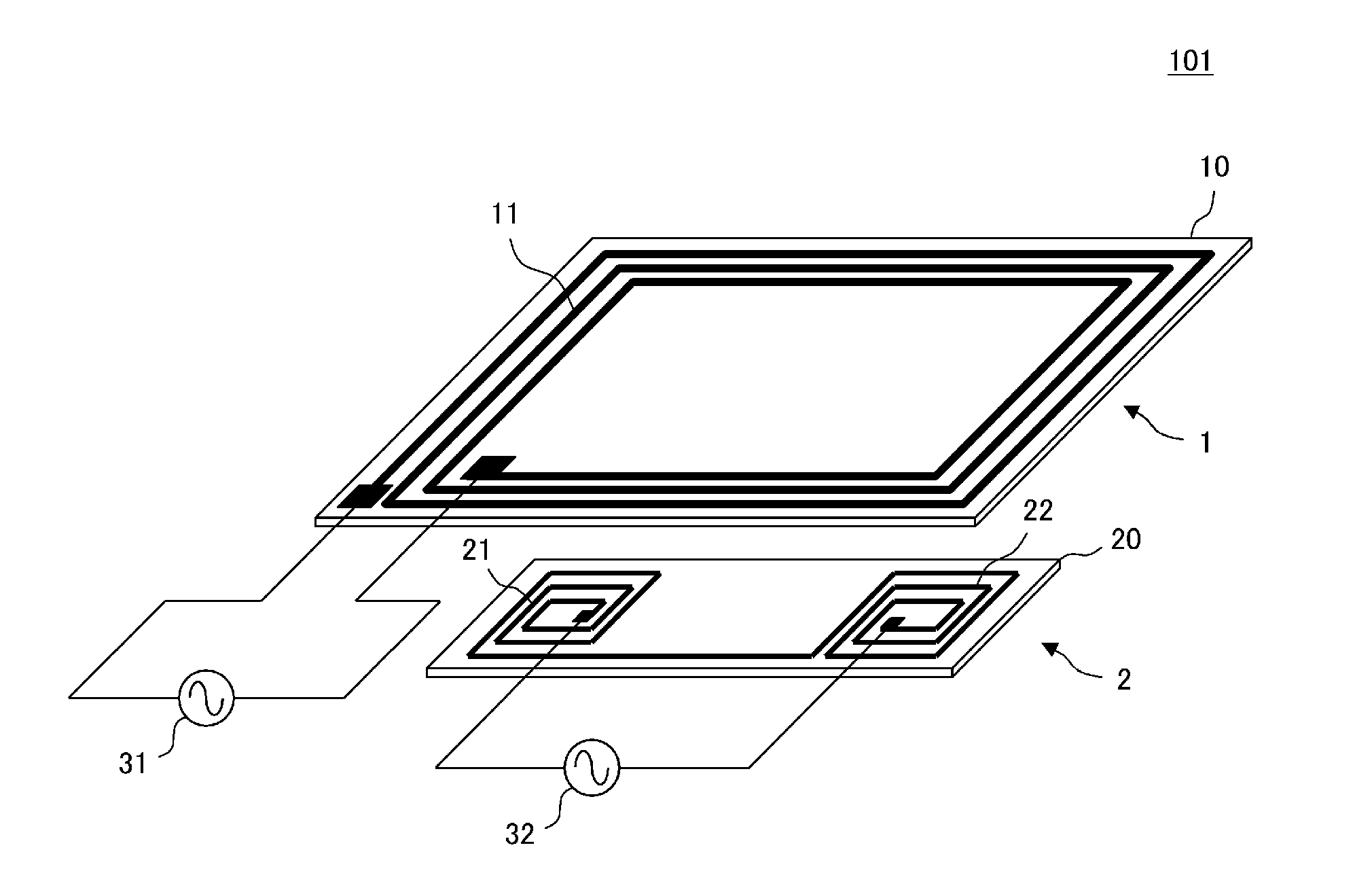
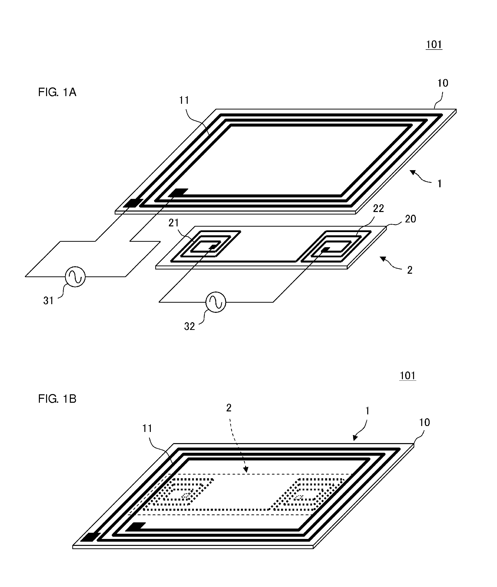
[0069]An antenna device 101 according to a first preferred embodiment will be described with sequential reference to the drawings.

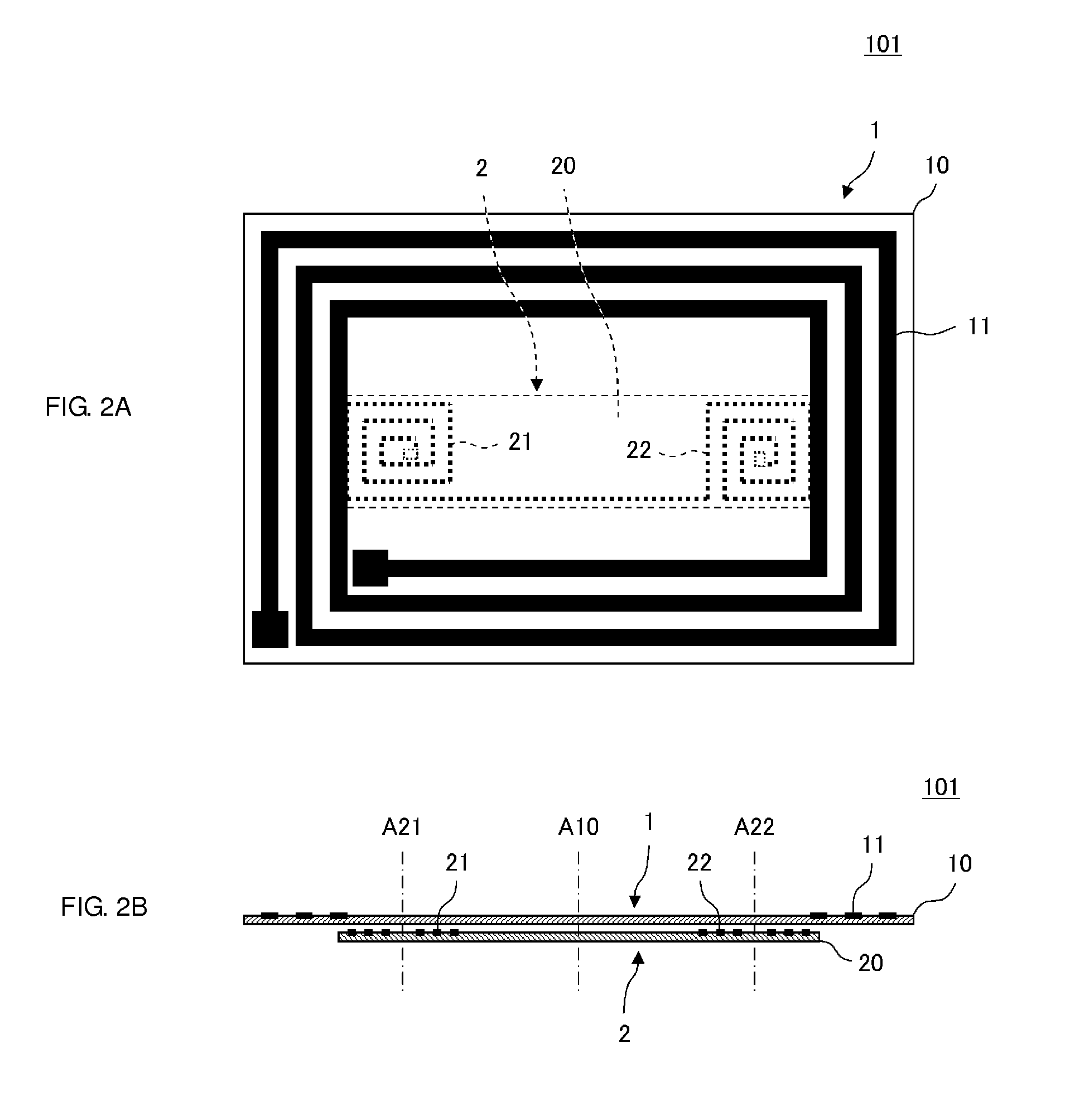
[0070]FIG. 1A is an exploded perspective view of the antenna device 101, and FIG. 1B is an external perspective view of the antenna device 101. This antenna device 101 includes a first coil antenna 1 and a second coil antenna 2. The first coil antenna 1 preferably is one in which a coil conductor 11 having a rectangular or substantially rectangular spiral shape is provided on a non-magnetic insulating base member 10. The second coil antenna 2 is one in which two coil conductors 21 and 22 are provided on a non-magnetic insulating base member 20. A first power supply circuit 31 is connected to the coil conductor 11 of the first coil antenna 1, and a second power supply circuit 32 is connected to the coil conductors 21 and 22 of the second coil antenna 2.

[0071]These two coil conductors 21 and 22 are disposed and wound such that a closed magnetic circuit (des...

second preferred embodiment

[0083]FIG. 6A is a plan view of an antenna device 102A of a second preferred embodiment of the present invention, and FIG. 6B is a front view of the antenna device 102A. FIG. 7A is a plan view of another antenna device 102B of the second preferred embodiment, and FIG. 7B is a front view of the antenna device 102B. FIG. 8 is a plan view of another antenna device 102C of the second preferred embodiment.

[0084]A difference from the antenna device 101 of the first preferred embodiment illustrated in FIG. 2 is the positional relationship between a first coil antenna 1 and a second coil antenna 2. In each of the antenna devices 102A, 102B, and 102C, the winding axis directions of winding axes of two coil conductors 21 and 22 of the second coil antenna 2 and the winding axis direction of a winding axis of the first coil antenna 1 match or substantially match one another (the winding axes are parallel or substantially parallel to one another). When seen in plan view from these winding axis d...

third preferred embodiment

[0087]FIG. 9A is an exploded perspective view of an antenna device 103 of a third preferred embodiment of the present invention, FIG. 9B is an external perspective view of the antenna device 103, FIG. 9C is a perspective view of an RFIC module 70 that is to be mounted in the antenna device 103, and FIG. 9D is a sectional view of the RFIC module 70. FIG. 10A is an exploded perspective view illustrating only coil conductors of a first coil antenna 1, and FIG. 10B is an equivalent circuit diagram of the first coil antenna.

[0088]Regarding the coil conductors of the first coil antenna 1, as illustrated in FIG. 10A, a top surface coil conductor 11A and a bottom surface coil conductor 11B are located on the front and rear sides of a base member 10. The winding direction of the top surface coil conductor 11A and the winding direction of the bottom surface coil conductor 11B are opposite to each other (are the same as each other in the perspective direction), and the top surface coil conduct...


PUM


Abstract

An antenna device includes a first coil antenna and a second coil antenna. The first coil antenna includes a coil conductor having a rectangular or substantially rectangular spiral shape and located on a non-magnetic insulating base member. The second coil antenna includes two coil conductors located on a non-magnetic insulating base member. The two coil conductors are disposed and wound such that loops of a magnetic field that is generated by applying a current to the two coil conductors are perpendicular or substantially perpendicular to a coil axis of the coil conductors.

Description

BACKGROUND OF THE INVENTION[0001]1. Field of the Invention[0002]The present invention relates to an antenna device and a wireless communication device preferably for use in an RFID system that includes a contactless IC card or an RF tag and the like.[0003]2. Description of the Related Art[0004]An RFID system in which a reader-writer and an RFID tag wirelessly communicate with each other in such a manner that information is transmitted between the reader-writer and the RFID tag has been widely used as an item management system. A reader-writer and an RFID tag are each formed of an RFID IC chip for processing a radio signal and an antenna for transmitting and receiving a radio signal, and a predetermined communication is performed between an antenna of a reader-writer and an antenna of an RFID tag via a magnetic field or an electromagnetic field.[0005]In recent years, an RFID system has been introduced in a wireless communication terminal as in, for example, Felica (Registered Tradema...

Claims


Application Information

Patent Timeline
IPC IPC(8): H01Q7/00H01Q21/28
CPCH01Q21/28H01Q7/00H01L2224/16225H01L2924/19105H01Q1/2208
Inventor KATO, NOBORUMIURA, TEPPEIOZAWA, MASAHIRO
Owner MURATA MFG CO LTD
Why Eureka
Try Eureka