Method for manufacturing electronic device, cover body, electronic device, electronic apparatus, and moving object

a manufacturing method and technology for electronic devices, applied in the direction of soldering apparatus, casing/cabinet/drawer details, electrical apparatus, etc., can solve the problems of unstable vibration characteristics, difficult to stably manage the dimension or the like of the unwelded portion, and achieve excellent reliability

Active Publication Date: 2014-05-29
SEIKO EPSON CORP
View PDF26 Cites 8 Cited by
  • Summary
  • Abstract
  • Description
  • Claims
  • Application Information

AI Technical Summary

Benefits of technology

[0046]According to this moving object, excellent reliability can be provided.

Problems solved by technology

Therefore, it is difficult to stably manage the dimension or the like of the unwelded portion.
Therefore, degassing and sealing cannot be stably performed, which may cause unstable vibration characteristics.

Method used


Image

  • Method for manufacturing electronic device, cover body, electronic device, electronic apparatus, and moving object
  • Method for manufacturing electronic device, cover body, electronic device, electronic apparatus, and moving object
  • Method for manufacturing electronic device, cover body, electronic device, electronic apparatus, and moving object

Examples


first embodiment

of Electronic Device

[0066]First, as a first embodiment of an electronic device manufactured by applying the method for manufacturing an electronic device according to the invention, an embodiment of a vibrator will be described.

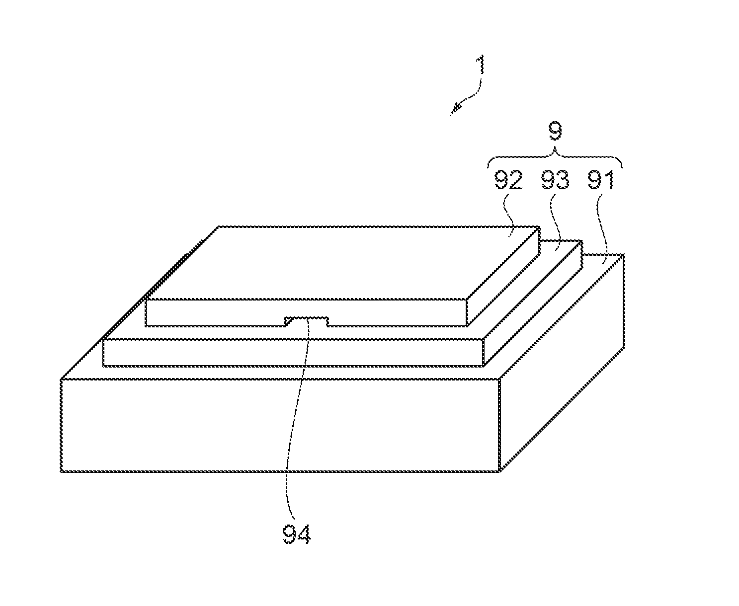
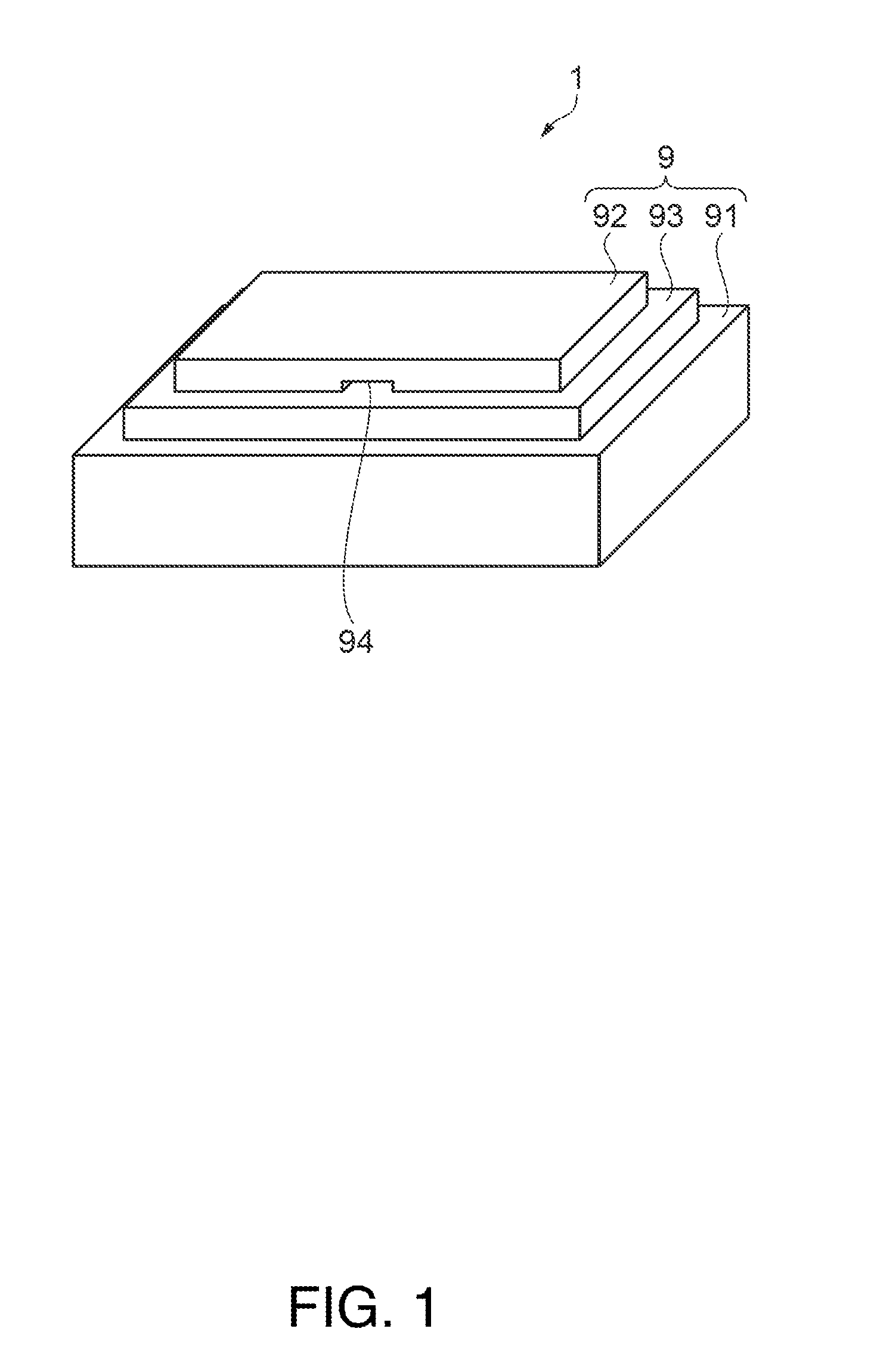
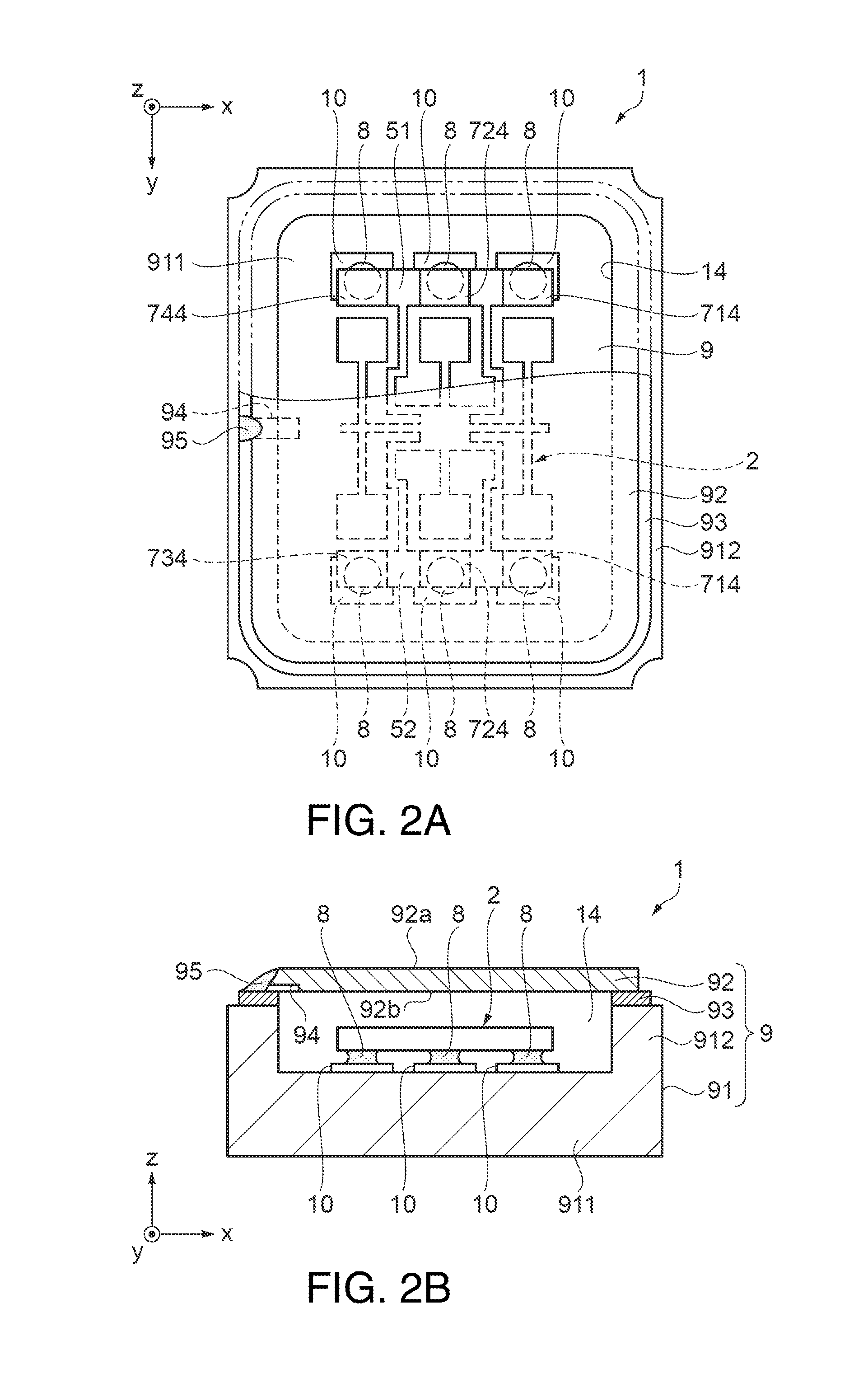
[0067]FIG. 1 is a schematic perspective view showing the vibrator as the first embodiment of the electronic device according to the invention. FIGS. 2A and 2B schematically show the vibrator as the first embodiment of the electronic device according to the invention, in which FIG. 2A is a plan view; and FIG. 2B is a front cross-sectional view. FIG. 3 is a plan view showing a gyro element as an electronic component included in the vibrator shown in FIGS. 2A and 2B. In the following as shown in FIGS. 2A and 2B, three axes orthogonal to each other are defined as an x-axis, a y-axis, and a z-axis. The z-axis coincides with a thickness direction of the vibrator. Moreover, a direction parallel to the x-axis referred to as “x-axis direction” (second direction)”; a d...

second embodiment

of Electronic Device

[0104]Next, as a second embodiment of an electronic device manufactured by applying a cover body according to the invention, an embodiment of a vibrator will be described. In the second embodiment, configurations similar to those of the first embodiment are denoted by the same reference numerals and signs, and the description thereof is omitted in some cases. FIGS. 8A and 8B schematically show the vibrator as an electronic device using a cover body according to the invention, in which FIG. 8A is a plan view; and FIG. 8B is a front cross-sectional view.

[0105]The vibrator 1 as an example of an electronic device shown in FIGS. 8A and 8B includes the gyro element (vibrating element) 2 as an element and the package 9 for accommodating the gyro element 2. Hereinafter, the gyro element 2 and the package 9 will be sequentially described in detail.

Gyro Element

[0106]The gyro element 2 used in the second embodiment has a configuration similar to that of the first embodiment...

modified example 1

of Lid

[0120]Modified Example 1 of a lid will be described according to FIG. 10A, in which the left part is a plan view; and the right part is a right side view. The lid 92 of Modified Example 1 has a configuration in which one bottomed groove is disposed in each of the first surface 92a and the second surface 92b.

[0121]Specifically speaking, the first groove 94a is disposed in the first surface 92a as a bottomed groove that is opened at one side portion of the circumferential surface of the lid 92 and disposed therefrom toward the center portion of the lid 92. In other words, the first groove 94a is disposed on the imaginary line C1 that passes through the center G of the first surface 92a and divides each of the first surface 92a and the second surface 92b into two portions, and arranged to be slightly shifted leftward in the drawing (negative y-axis direction) with respect to the imaginary line C1.

[0122]On the side opposite to the first surface 92a, that is, in the second surface...


PUM

PropertyMeasurementUnit
width L1aaaaaaaaaa
depth L2aaaaaaaaaa
areaaaaaaaaaaa

Abstract

A method for manufacturing an electronic device is provided, in which a base and a lid as a cover body are bonded together while forming an interior space between the base and the lid. The method includes: a step of preparing the lid including a groove communicating the interior space with the outside, the groove being in a back surface of the lid; a step of accommodating a gyro element as an electronic component in the interior space; a first bonding step of bonding the base and the lid together by seam welding at an area for bonding except for a portion corresponding to the groove; and a second bonding step of bonding the base and the lid by welding using a laser beam at a portion of the area for bonding, the portion including an end of the groove on the outside side, to thereby close the groove.

Description

BACKGROUND[0001]1. Technical Field[0002]The present invention relates to a method for manufacturing an electronic device, a cover body, an electronic device, an electronic apparatus, and a moving object.[0003]2. Related Art[0004]In recent years, as mobile electronic apparatuses have become widespread, reductions in size, weight, and cost of the electronic apparatuses are increasingly demanded. Therefore, also for electronic components used in the electronic apparatuses, reductions in size and cost, with maintaining of high accuracy, are increasingly demanded. Especially in a vibrating device having a vibrating element accommodated in a package, since vibration characteristics are maintained by maintaining the hermeticity of a space in which the vibrating element is accommodated, various proposals have been made for the sealing technique of the space.[0005]For example, JP-A-2000-223604 and JP-A-2002-359311 each disclose a bonding method, in which a lid for covering an opening of a sp...

Claims


Application Information

Patent Timeline
Patent Type & Authority Applications(United States)
IPC IPC(8): H05K5/03H05K5/00
CPCH03H9/1014B23K26/21B23K26/211B23K26/22H01L2224/16H01L2924/1461H01L2924/16195H03H9/1057H03H9/1071H01L2924/00
Inventor AOKI, SHINYASHIMURA, MASASHI
Owner SEIKO EPSON CORP
Why Eureka
Try Eureka