Phase contrast imaging apparatus

Active Publication Date: 2014-05-29
KONINKLJIJKE PHILIPS NV
View PDF8 Cites 40 Cited by
  • Summary
  • Abstract
  • Description
  • Claims
  • Application Information

AI Technical Summary

Benefits of technology

[0021]According to another embodiment, the detector (105) is adapted to count photons impinging on the detector strips (105a) and generate a signal corresponding to the energy of impinging photons, and wherein a control unit (121) is adapted to receive said signals and assign a weight to the phase-contrast image effect in relation to the efficiency at each energy and/or wherein the control unit 121 is adapted to assign a weight to the phase-contrast image

Problems solved by technology

Medical x-ray imaging is often limited by small contrast differences and high noise caused by tight dose restraints.
This is particularly true for mammography where low contrast tumors constitute a major detection target, and a large number of tumors are missed or misdiagnosed due to difficulties in detection.
First of all, the solution requires the manufacturing of physically long sub-gratings G1n and G2n, which is consumes resources in terms of cost and time.
Another drawback is that the proposed set up if directly implemented in

Method used


Image

  • Phase contrast imaging apparatus
  • Phase contrast imaging apparatus
  • Phase contrast imaging apparatus

Examples


Example

[0050]In the following, a detailed description of the invention will be given.

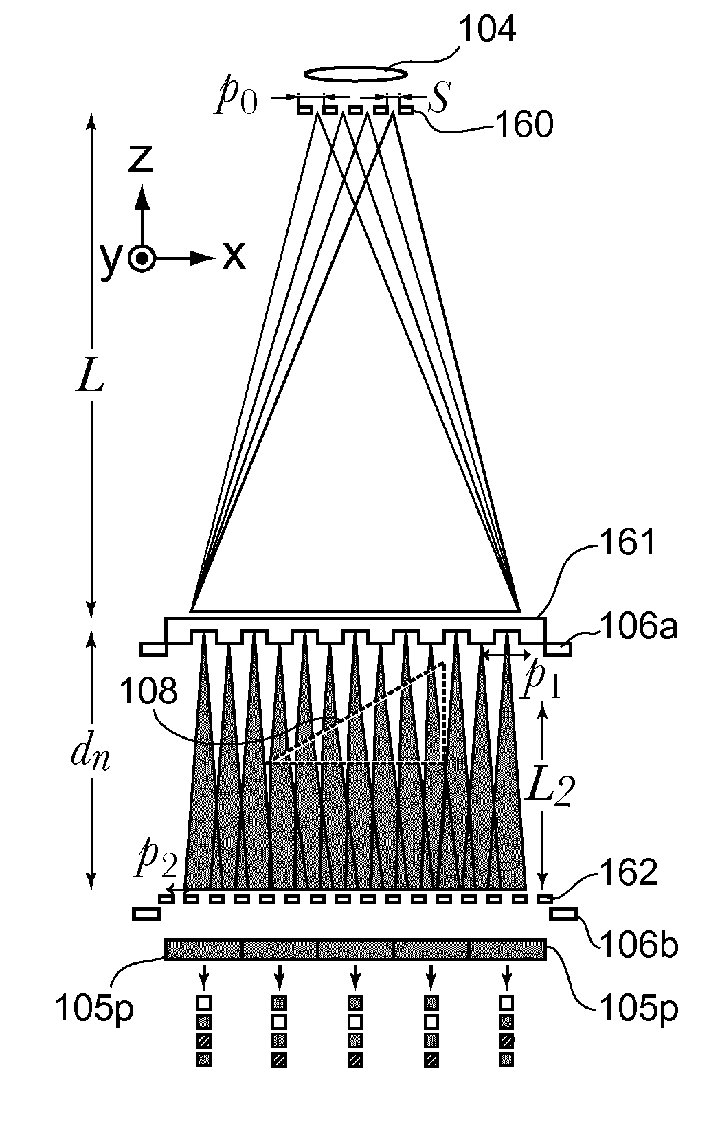
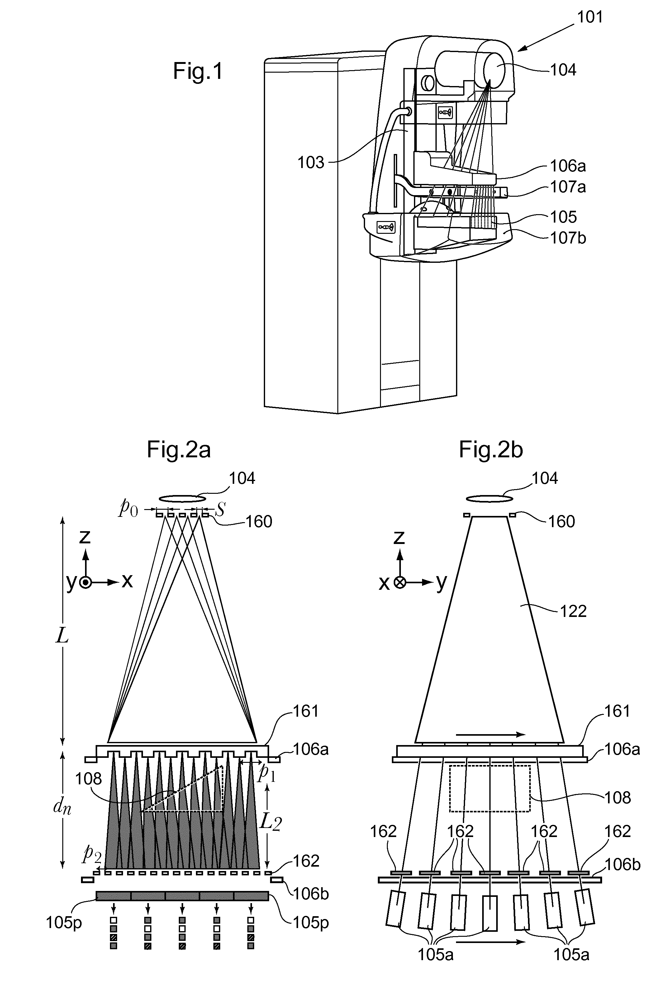
[0051]FIG. 1 illustrates an x-ray imaging system 101 according to one embodiment, based on a photon-counting detector 105 that scans the image field in one direction. The system according to this embodiment is based on the existing scanning systems for x-ray imaging developed by the applicant, whereby the system have the same external features as are for instance known from document U.S. Pat. No. 7,496,176. The system thus comprises an x-ray source 104 arranged in a housing, patient support and pre-collimator 106a housing and compression paddle 107a, 107b. A collimator is arranged in a collimator support, and the patient support comprises a detector 105 comprising a plurality of detector strips 105a. The x-ray source 104 and the detector 105 are arranged essentially in respective ends of a scan arm 103, hence arranged to be displaced radially with the x-ray source 104 in the centre. An image is acquired by...


PUM


Abstract

An x-ray imaging system comprising an x-ray source, an x-ray detector comprising a plurality of detector strips arranged in a first direction of the x-ray detector, each detector strip further comprising a plurality of detector pixels arranged in a second direction of the x-ray detector; a phase grating; a plurality of analyzer gratings comprising grating slits; a phase grating, and a plurality of analyzer gratings comprising grating slits, wherein the x-ray source and the x-ray detector are adapted to perform a scanning movement in relation to an object in the first direction, in order to scan the object, wherein the analyzer gratings are arranged between the x-ray source and the x-ray detector, wherein each of the plurality of analyzer gratings (162) is arranged in association with a respective detector strip with the grating slits arranged in the second direction and wherein the grating slits of the analyzer gratings of the detector strips are displaced relative to each other in the second direction.

Description

TECHNICAL FIELD[0001]The present invention relates generally to an improved x-ray imaging apparatus in the field of mammography, tomosynthesis, radiography, wherein phase contrast imaging capabilities have been implemented.BACKGROUND ART[0002]In prior art it has been proposed to use phase contrast in x-ray imaging to increase signal-to-noise ratio (SNR) in e.g. mammographic applications. Medical x-ray imaging is often limited by small contrast differences and high noise caused by tight dose restraints. This is particularly true for mammography where low contrast tumors constitute a major detection target, and a large number of tumors are missed or misdiagnosed due to difficulties in detection. The use of phase contrast imaging in medical applications have shown promising in order to increase SNR, since the phase shift in soft tissue is in many cases substantially larger than the absorption.[0003]International patent application WO 2008 / 006470 A1 describes the use of interferometers ...

Claims


Application Information

Patent Timeline
IPC IPC(8): A61B6/00
CPCA61B6/484A61B6/0414A61B6/06A61B6/4233A61B6/4241A61B6/4291A61B6/4441A61B6/482A61B6/502A61B6/5205A61B6/582
Inventor FREDENBERG, ERIKASLUND, MAGNUS
Owner KONINKLJIJKE PHILIPS NV
Why Eureka
Try Eureka