Drive system for a motor vehicle

Inactive Publication Date: 2014-06-05
ROBERT BOSCH GMBH
View PDF8 Cites 6 Cited by
  • Summary
  • Abstract
  • Description
  • Claims
  • Application Information

AI Technical Summary

Benefits of technology

The present invention provides a new way to check the pressure difference in an exhaust gas recirculation system. This approach is cost-effective while still delivering accurate results.

Problems solved by technology

In the case of exhaust gas recirculation in the low-pressure region, the pressure differences are small, so that a detection of the pressure difference is made more difficult.
However, the drawback is that very high temperatures may be present at the measuring points due to the hot exhaust gas, which may result in damage to the sensor system.
The use of the turbocharger causes the exhaust gas from the turbine to be particularly hot, and at the same time the pressure difference in the exhaust gas recirculation system is particularly small.

Method used


Image

  • Drive system for a motor vehicle
  • Drive system for a motor vehicle

Examples


Embodiment Construction

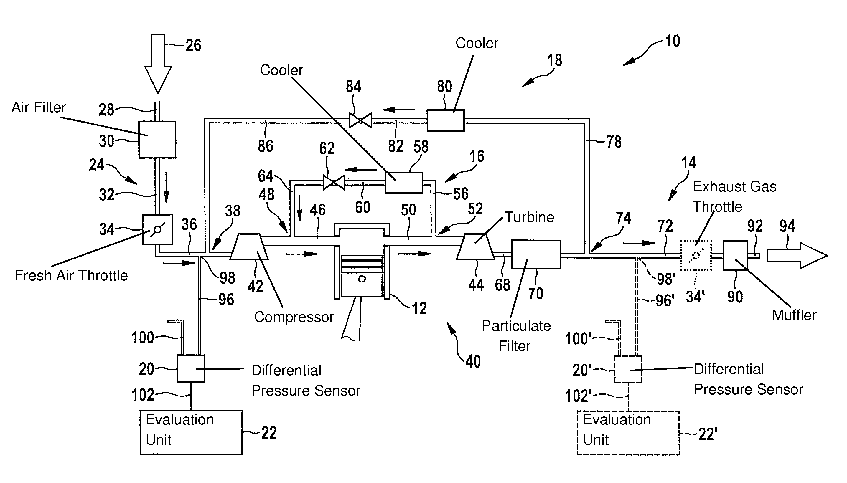
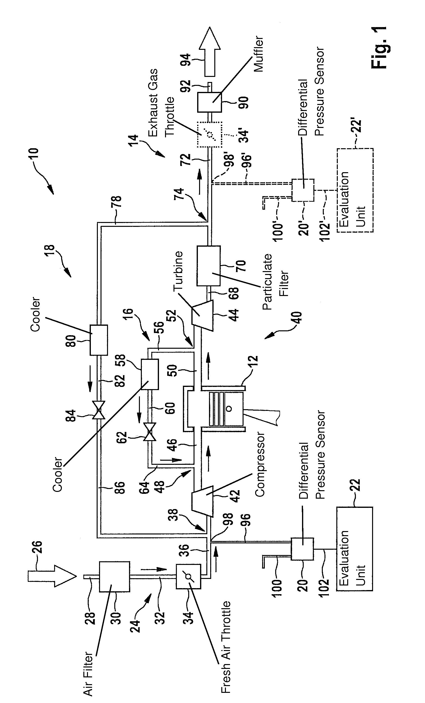
[0044]The FIGURE, reference numeral 10 denotes a drive system for a motor vehicle as a whole. Drive system 10 includes an internal combustion engine 12, an air and exhaust gas system 14, a high-pressure exhaust gas recirculation system 16, and an exhaust gas recirculation system 18 in a low-pressure region. In addition, drive system 10 includes a differential pressure sensor 20 and a control and evaluation unit 22.

[0045]Air and exhaust gas system 14 includes an air supply unit 24, via which fresh air 26 is taken in. Fresh air 26 is conducted to an air filter 30 via an intake pipe 28. Fresh air 26 flows from air filter 30 through a line 32 to a fresh air throttle 34. Proceeding from fresh air throttle 34, fresh air 26 flows into a further line 36, which includes a supply point 38. Supply point 38 is an opening of exhaust gas recirculation system 18 into air supply unit 24. Exhaust gas flows from supply point 38 into line 36.

[0046]Air supply unit 24 is in fluidic connection with a tur...


PUM


Abstract

A drive system for a motor vehicle, having an internal combustion engine, an air and exhaust gas system, which includes at least one throttle, an exhaust gas recirculation system, which is in fluidic connection with the air and exhaust gas system at two connecting points, and a measuring device, which is designed to detect an atmospheric pressure, to detect a gas pressure at a measuring point within the air and exhaust gas system, and to ascertain a differential pressure as a function of the gas pressure and the atmospheric pressure, the measuring point being fluidically situated between the throttle and the internal combustion engine and in a region of one of the connecting points.

Description

FIELD OF THE INVENTION[0001]The present invention relates to a drive system for a motor vehicle, having an internal combustion engine, an air and exhaust gas system, which includes at least one throttle, an exhaust gas recirculation system, which is in fluidic connection with the air and exhaust gas system at two connecting points, and a measuring device, which is designed to detect an atmospheric pressure, to detect a gas pressure at a measuring point within the air and exhaust gas system, and to ascertain a differential pressure as a function of the gas pressure and the atmospheric pressure, the measuring point being fluidically situated between the throttle and the internal combustion engine and in a region of one of the connecting points.[0002]The present invention further relates to a method for operating a drive system for a motor vehicle, having an internal combustion engine, an air, and exhaust gas system, which includes a throttle, an exhaust gas recirculation system, which...

Claims


Application Information

Patent Timeline
IPC IPC(8): F02D41/00
CPCF02D41/005F02D41/0002F02D41/0065F02D41/1448F02D2200/0406F02D2200/703F02M26/05F02M26/06F02M26/47Y02T10/40F02D41/00
Inventor BLUMENDELLER, WILHELMBLEILE, THOMAS
Owner ROBERT BOSCH GMBH
Why Eureka
Try Eureka