Transmission line and antenna device

a technology of transmission line and antenna device, which is applied in the direction of stripline fed array, particular array feeding system, waveguide, etc., can solve the problems of unstable characteristics of a triplate line of this type, impedance mismatch and reflection of high-frequency signals, and it is difficult in practice to provide such a through hole in the supported portion. 122, the effect of ensuring the strength of the supported portion

Inactive Publication Date: 2014-06-05
HITACHI METALS LTD
View PDF6 Cites 3 Cited by
  • Summary
  • Abstract
  • Description
  • Claims
  • Application Information

AI Technical Summary

Benefits of technology

[0011]An object of the present invention is to provide a transmission line and an antenna device that can reduce reflections while ensuring strength in a supported portion of a central conductor.
[0013]According to the present invention, it is possible to reduce reflections while ensuring strength in the supported portion of the central conductor.

Problems solved by technology

Characteristics of a triplate line of this type tend to be unstable, due to positional displacement of a central conductor or changes in distance between outer conductors.
This results in an impedance mismatch and reflection of high-frequency signals.
Because this may affect the mechanical strength of the supported portion, it has been difficult in practice to provide such a through hole in the supported portion.

Method used


Image

  • Transmission line and antenna device
  • Transmission line and antenna device
  • Transmission line and antenna device

Examples


example 1

[0058]FIG. 7A is an external perspective view of a triplate line 100A according to Example 1 of the present invention. FIG. 7B is an enlarged view of a main part of the triplate line 100A.

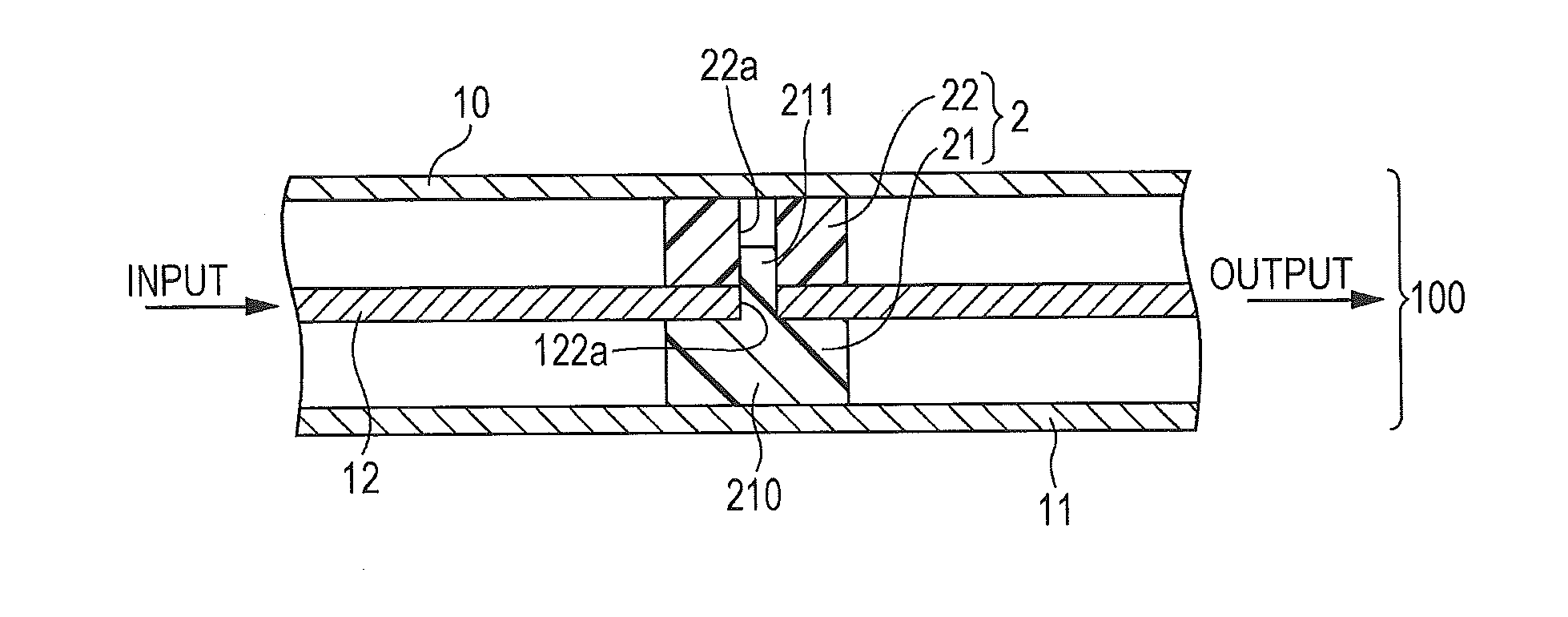
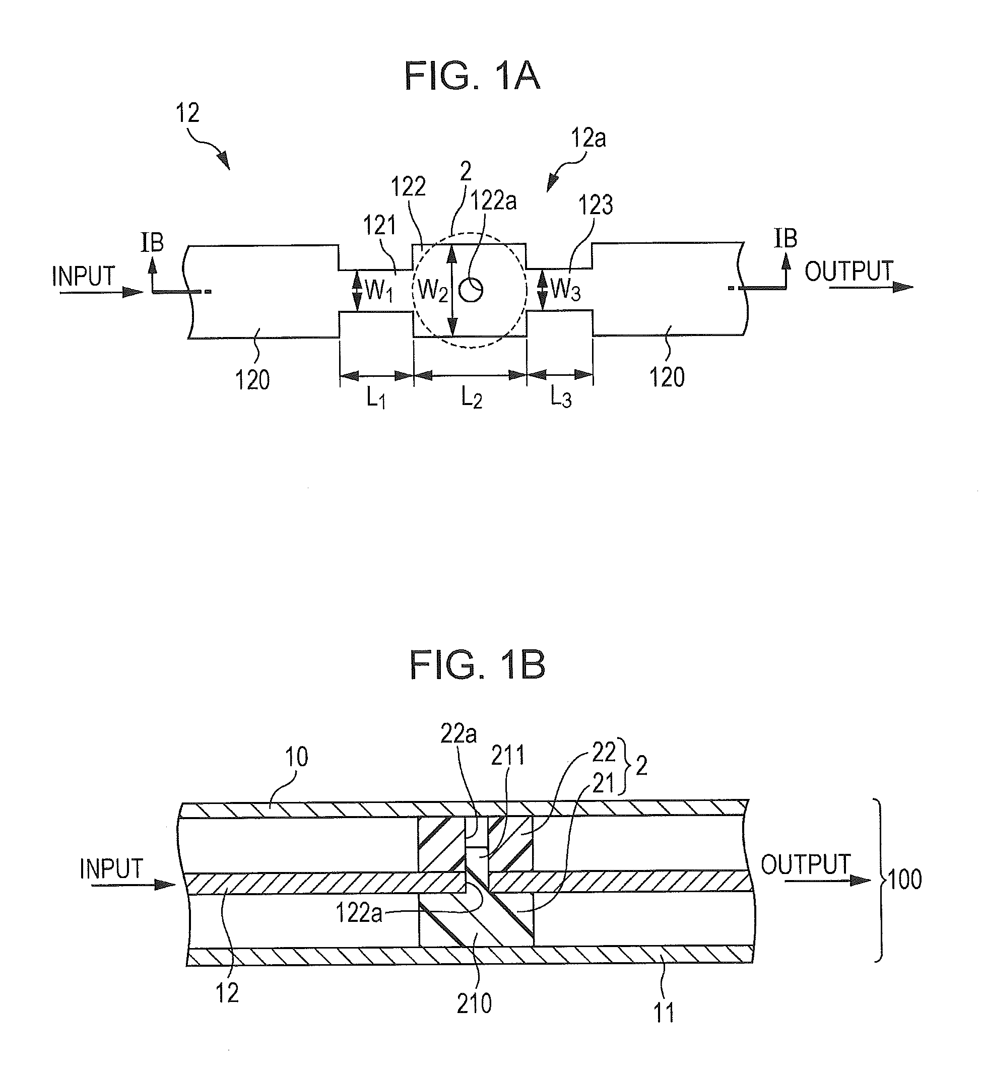
[0059]As illustrated in FIG. 7A, the triplate line 100A is formed by the first and second outer conductors 10 and 11, and the central conductor 12 having a long narrow plate-like shape. A distance between the first outer conductor 10 and the second outer conductor 11 is 5 mm, and a thickness of the central conductor 12 is 1 mm. The central conductor 12 has, in its center, the supported portion 122 and the first and second high-impedance portions 121 and 123 similar to those illustrated in FIG. 1A. The supported portion 122 has the through hole 122a (see FIG. 7B) having a diameter D of 2 mm. The supported portion 122 is supported by the dielectric spacer 2 having a structure similar to that of the dielectric spacer 2 illustrated in FIG. 1B.

[0060]The line width W1 and the line length L1 of the first ...

example 2

[0065]FIG. 9A schematically illustrates a configuration of a triplate line 100B according to Example 2. FIG. 9B shows measured VSWRs.

[0066]The central conductor 12 of the triplate line 100B extends from a first terminal portion P1, through the support structure part 12a, and is divided into a second terminal portion P2 and a third terminal portion P3. A portion between the second terminal portion P2 and the third terminal portion P3 extends linearly, and there is a T-shaped branch portion P0 between the second terminal portion P2 and the third terminal portion P3. The first high-impedance portion 121 is disposed on one side of the supported portion 122 adjacent to the first terminal portion P1, and the second high-impedance portion 123 is disposed on the other side of the supported portion 122 adjacent to the branch portion P0. The central conductor 12 is disposed between the first outer conductor 10 and the second outer conductor 11 (not shown).

[0067]For the triplate line 100B, a s...


PUM


Abstract

A transmission line has a triplate line including a first outer conductor and a second outer conductor disposed in parallel with each other at a predetermined interval, and a central conductor disposed in a space between the first outer conductor and the second outer conductor; and a dielectric spacer interposed between the first and second outer conductors and the central conductor and configured to support the central conductor. The central conductor has a supported portion supported by the dielectric spacer, and first and second high-impedance portions having characteristic impedances higher than a characteristic impedance in the supported portion. The first and second high-impedance portions are disposed on input and output sides, respectively, of the supported portion.

Description

[0001]The present application is based on Japanese patent application No. 2012-264582 filed on Dec. 3, 2012, the entire contents of which are incorporated herein by reference.BACKGROUND OF THE INVENTION[0002]1. Field of the Invention[0003]The present invention relates to a transmission line and an antenna device including the transmission line.[0004]2. Description of the Related Art[0005]In an antenna device for a radio communication apparatus, such as a mobile terminal, a transmission line for transmitting high-frequency signals has been used, which forms a distributor or a multiplexer between a high-frequency power source and a transmitting / receiving device. Examples of the transmission line include a microstrip line and a triplate line, which is formed by a pair of outer conductors disposed in parallel with each other and a plate-like central conductor interposed therebetween (see, e.g., Japanese Unexamined Patent Application Publication No. 2003-264420).[0006]A triplate line des...

Claims


Application Information

Patent Timeline
Patent Type & Authority Applications(United States)
IPC IPC(8): H03H7/38H01P3/00H01Q1/50
CPCH01P3/085H01P3/087H01Q21/0081H01Q21/08H01Q1/50
Inventor ISO, NAOKIKITANO, NOBUAKI
Owner HITACHI METALS LTD
Why Eureka
Try Eureka