Temperature control system

a temperature control and temperature technology, applied in the field of temperature control systems, can solve the problems of unstable control and unstable amount of generated vapor, and achieve the effects of avoiding complex structure and enlargement of equipment, high accuracy and precision, and uniform temperature in the refrigerant drum

Inactive Publication Date: 2014-06-12
JAPAN PETROLEUM EXPLORATION CO LTD +5
View PDF10 Cites 4 Cited by
  • Summary
  • Abstract
  • Description
  • Claims
  • Application Information

AI Technical Summary

Benefits of technology

[0026]The temperature control system according to the present invention is provided with the Replenishing line that supplies makeup water in an amount matched with an amount of vapor discharged to the outside of the system, to the Return line that returns mixed phase fluid of vapor and the liquid refrigerant generated in the heat removing section in the reactor, to the refrigerant drum. Accordingly, makeup water in an amount matched with the amount of vapor discharged to the outside of the system, is merged into the Return line and directly mixed with vapor in the Return line at saturation temperature, thereby enabling to heat the makeup water to saturation temperature before being supplied to the refrigerant drum. As a result, the gas-liquid temperature in the refrigerant drum can be maintained at saturation temperature at all times.
[0027]Moreover, as compared with the conventional temperature control system in which the makeup water is directly supplied to the refrigerant drum, the complexity of the structure and enlargement of the equipment can be avoided, and the temperature in the refrigerant drum can be made uniform.
[0028]As a result, since the temperature in the refrigerant drum can be made uniform efficiently, temperature control of the reactor can be performed with high accuracy and precision.
[0029]Moreover, the temperature control system includes: the control unit that determines the amount of makeup water by dividing the reaction heat in the reactor by heat capacity per unit quantity of refrigerant determined based on the difference between a comparatively high temperature in the refrigerant drum and a comparatively low temperature of makeup water, and physical values (specific heat, evaporative latent heat) of the refrigerant; and the makeup water adjusting device that sets the amount of makeup water to be supplied from the Replenishing line to the Return line according to the amount of makeup water determined by the control unit. Consequently, the control unit can accurately calculate the amount of makeup water so as to be equal to a flow rate of vapor supplied to the outside of the system, and can accurately limit the amount of makeup water so as not to exceed the flow rate of vapor. As a result, hammering due to complete condensation at the junction can be reliably prevented.
[0030]Because the amount of makeup water determined by the control unit is specifically calculated according to the following equation, the amount of makeup water can be accurately calculated so as to be equal to the flow rate of vapor supplied to the outside of the system, and can be limited so as not to exceed the flow rate of vapor.
[0036]Moreover, in the temperature control system according to the present invention, the Replenishing line is connected to the Return line at an acute angle along the traveling direction of mixed phase fluid at the junction of the Return line and the Replenishing line. Consequently, makeup water in the Replenishing line can be supplied along a flow direction of the mixed phase fluid at the time of merging makeup water to the mixed phase fluid of vapor into the liquid refrigerant in the Return line. As a result, generation of hammering due to an impact when makeup water collides with the mixed phase fluid at the time of joining can be prevented.

Problems solved by technology

Hence, if this configuration is applied to temperature control of an FT (Fisher-Tropsch) reactor, control becomes unstable.
Moreover, there is another problem in that the amount of generated vapor becomes unstable because the temperature of the liquid phase decreases due to the amount of water supplied to the steam drum.

Method used


Image

  • Temperature control system
  • Temperature control system
  • Temperature control system

Examples


example

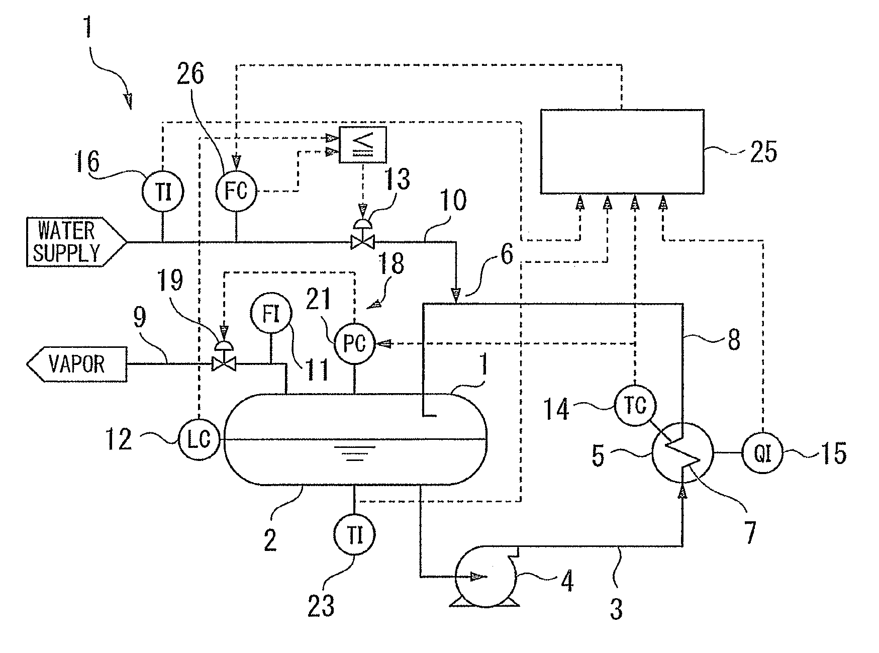
[0094]Next is a description of an example of the temperature control system 1 according to an embodiment of the present invention.

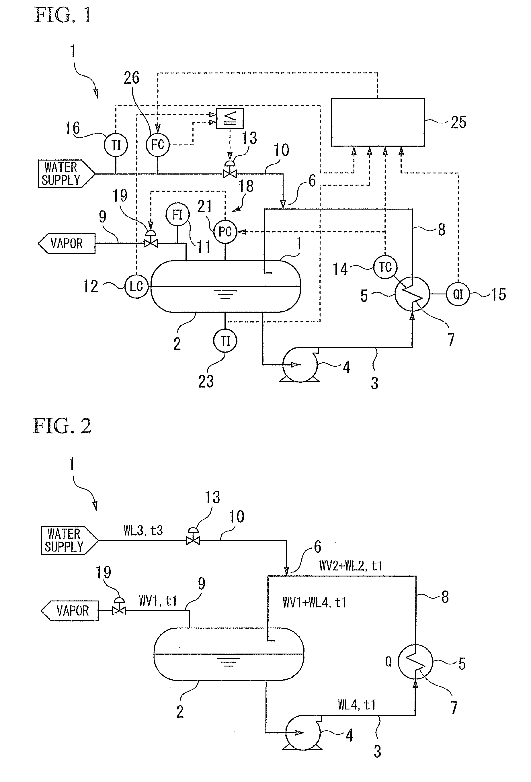
[0095]First, in FIG. 2, it is assumed that the temperature inside the steam drum 2, the respective water temperatures t1 of the water to be supplied at the flow rates WL4 and WL2 via the supply line 3, and the temperature t1 of vapor at the flow rates WV1 and WV2 are all a saturation temperature of 195° C. It is also assumed that the water temperature t3 of the makeup water in the amount of WL3 is 110° C.

[0096]Moreover, it is assumed that

[0097]reaction heat Q=8000000 kcal / h

[0098]evaporative latent heat of water r=470 kcal / kg (physical property (constant))

[0099]specific heat Cp of water=1 kcal / kg / ° C. (physical property (constant))

[0100]pressure in steam drum=1.3 MPaG

[0101]circulation amount WL4 of water supply pump 4=68000 kg / h.

[0102]Under the above conditions, the control unit 25 of the temperature control system 1 determines the amount of makeup water W...


PUM


Abstract

A temperature control system of the invention recovers reaction heat in a reactor in which an exothermal reaction occurs, to control the temperature in the reactor. The temperature control system includes: a refrigerant drum in which vapor and a liquid refrigerant are stored in a vapor-liquid equilibrium state; a heat removing section arranged in the reactor to evaporate a part of the liquid refrigerant supplied from the refrigerant drum by the reaction heat; a Return line that returns mixed phase fluid of vapor and the liquid refrigerant generated in the heat removing section to the refrigerant drum; a Vapor outlet line that supplies vapor in the refrigerant drum to outside of the system; and a Replenishing line that supplies makeup water in an amount matched with an amount of vapor discharged to the outside of the system, to the Return line.

Description

CROSS-REFERENCE TO RELATED APPLICATION[0001]This application is a Section 371 of International Application No. PCT / JP2012 / 069692, filed Aug. 2, 2012, which was published in the Japanese language on Feb. 14, 2013, under International Publication No. WO 2013 / 021908 A1, and the disclosure of which is incorporated herein by reference.TECHNICAL FIELD[0002]The present invention relates to a temperature control system that can perform precise temperature control of a reactor by making the temperature in a refrigerant drum such as a steam drum uniform.[0003]Priority is claimed on Japanese Patent Application No. 2011-171812, filed Aug. 5, 2011, the content of which is incorporated herein by reference.BACKGROUND ART[0004]Conventionally, as a water supply system for a steam drum, there are those described for example in Patent Documents 1 and 2. The water supply system described in Patent Document 1 supplies water to a drum via a water supply line from an economizer upon reception of flue gas,...

Claims


Application Information

Patent Timeline
Patent Type & Authority Applications(United States)
IPC IPC(8): F25D7/00F28B9/04F28B11/00F25D1/02F28B9/02
CPCF25D7/00F25D1/02F28B9/04F28B9/02F28B11/00F22B35/00B01J8/22B01J8/001B01J2208/00061B01J2208/00115B01J2219/002B01J2219/00211B01J2219/00238C10G2/32
Inventor KATO, YUZURUYAMADA, EIICHIMORITA, KENTAROU
Owner JAPAN PETROLEUM EXPLORATION CO LTD
Why Eureka
Try Eureka