Rotary workhead device

Active Publication Date: 2014-06-12
MAKINO MILLING MASCH CO LTD
View PDF20 Cites 2 Cited by
  • Summary
  • Abstract
  • Description
  • Claims
  • Application Information

AI Technical Summary

Benefits of technology

[0012]According to this feature, a workpiece can be processed while tensile or compressive force is applied to the workpiece whereby the rigidity of the workpiece is apparently increased. Therefore, even a thin and low rigidity workpiece, such as a turbine blade, can be successfully processed because the bending is very small and vibrations are not generated.
[0013]It is not necessary to form a hydraulic cylinder in a tailstock, as described in patent document 1, because the means for biasing one of the two rotary workheads in the direction away from or toward the other rotary workhead can

Problems solved by technology

In addition, a special tail stock, incorporated with a hydraulic cylinder, must be produced, resulting in remarkably increased cost.
Further, similar to the invention of Patent Doc

Method used


Image

  • Rotary workhead device
  • Rotary workhead device
  • Rotary workhead device

Examples


second embodiment

[0048]The functional operation of the second embodiment will be described below.

first embodiment

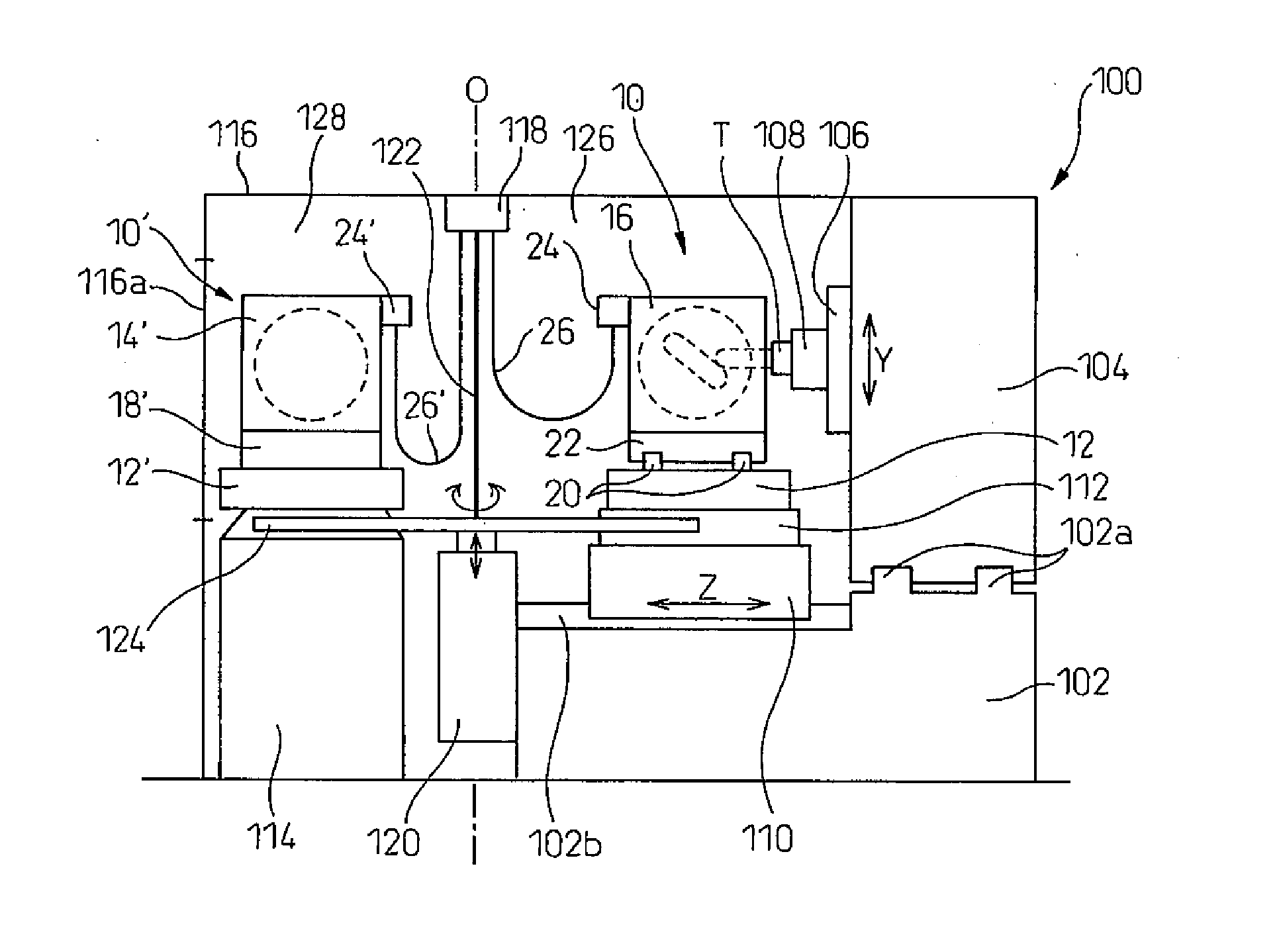
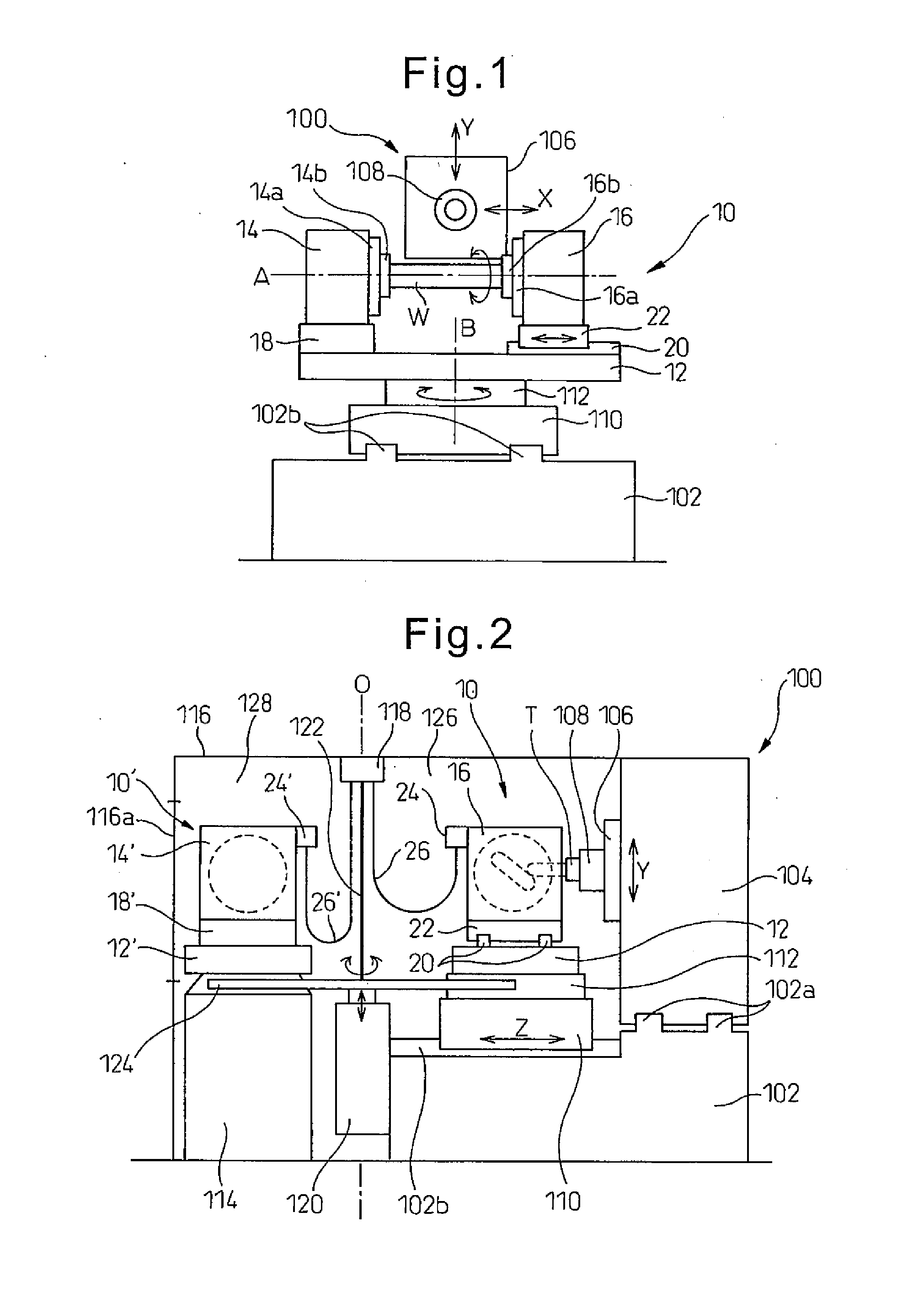
[0049]Similar to the first embodiment, when a workpiece W is processed in the machining chamber 126 of the machine tool 100, an operator of the machine tool 100 can open the front door to access the preparation chamber 128 in order to remove a processed workpiece from and to mount a new and non-processed workpiece to the rotary workhead device. For this purpose, the operator closes the on-off valve 76 to block the pneumatic pressure applied to the air brakes 72 from the pneumatic pressure source 74 so that the air brakes are unclamped. This allows the rotary workhead 16 to be manually moved along the guide rails 20. Then, the workpiece W is removed from the rotary workhead device by loosening the fixtures 14b and 16b, e.g., chucks.

[0050]Thereafter, a new and non-processed workpiece is mounted to the fixtures 14b and 16b. At that time, an operator can manually move the movable rotary workhead 16 along the guide rails 20 so as to adjust the distance between the movable and stationary ...


PUM

PropertyMeasurementUnit
Forceaaaaaaaaaa
Pressureaaaaaaaaaa
Tensile propertiesaaaaaaaaaa

Abstract

The rotary workhead device, which is loaded on the table of a machine tool and onto which a workpiece to be machined is rotatably mounted, is equipped with: a base plate that is attached to the table of the machine tool; two rotary workheads that are provided on the base plate and disposed so that the axes of rotation coincide and the workpiece-fixing parts face each other; a guide means that is provided so as to be capable of moving at least one of the rotary workheads back and forth in the direction of the rotation axes; and an impelling means for impelling the one rotary workhead in a direction that separates or brings together the two rotary workheads. The rotary workhead device applies a tensile force or a compressive force on a workpiece, the respective ends of which are fixed between the two rotary workheads.

Description

REFERENCE TO RELATED APPLICATION[0001]This application is the national stage application under 35 USC 371 of International Application No. PCT / JP2011 / 066772, filed Jul. 15, 2011, the entire contents of which are incorporated herein by reference.FIELD OF THE INVENTION[0002]The invention relates to a rotary workhead for machine tools which process workpieces with tensile or compressive force applied on the workpieces.BACKGROUND OF THE INVENTION[0003]Conventionally, in order to produce curved surfaces on workpieces, machine tools having a plurality of feed axes are used. When a thin and fragile workpiece, such as turbine blades for steam or gas turbines is processed, it is necessary to prevent deformation of the workpiece due to machining force and vibrations generated from the contact between the tool and the workpiece.[0004]Patent Document 1 describes a method and an apparatus for machining turbine blades. In the invention of Patent Document 1, one end of a workpiece is secured to a ...

Claims


Application Information

Patent Timeline
IPC IPC(8): B23Q1/26
CPCB23Q1/26B23Q3/063B23Q11/0032B23Q3/066B23Q1/52Y10T82/2572Y10T29/5114Y10T409/305824Y10T29/5196B23C2215/44B23C1/14
Inventor SHIRONE, MASAHIRO
Owner MAKINO MILLING MASCH CO LTD
Why Eureka
Try Eureka