Mask assembly for thin film vapor deposition and manufacturing method thereof

a technology of thin film vapor deposition and mask assembly, which is applied in the field of mask assembly, can solve the problems of increasing the etching error of forming the pattern opening, the inability to control the tensile force of the mask fixed to the frame, and the time and effort required to extend the mask and weld the mask to the frame, so as to reduce the pattern opening and the accuracy of the pixel position, reduce the production cost, and improve the quality of the produ

Active Publication Date: 2014-06-12
SAMSUNG DISPLAY CO LTD
View PDF3 Cites 15 Cited by
  • Summary
  • Abstract
  • Description
  • Claims
  • Application Information

AI Technical Summary

Benefits of technology

[0009]The described technology has been made in an effort to provide a mask frame for controlling a tensile force of a mask when the mask is fixed to the frame and reducing a number of discarded masks, and a manufacturing method thereof.
[0035]The mask assembly controls the tensile force of a mask that has generated a problem during the welding process and a mask of which uniformity of the pattern opening and accuracy of the pixel position are reduced, thereby repairing the same and acquiring a good quality product. Therefore, the number of discarded masks is reduced to reduce the production cost, and the time for replacing the mask is reduced to increase the time for consecutively operating the depositor, thereby increasing productivity.

Problems solved by technology

As the mask is enlarged, an etching error for forming the pattern opening can be increased and the center of the mask can droop by self-gravitation, so the mask is fixed to the frame through welding while a tensile force is applied to the mask.
However, it is then impossible to control the tensile force of the mask fixed to the frame.
Adversely, much time and effort are required to extend the mask and weld the mask to the frame, and moreover, a mask having a problem during the extending and welding is discarded.
Further, a mask used for the deposition process may generate a problem of reducing uniformity of the pattern opening and accuracy of the pixel position.

Method used


Image

  • Mask assembly for thin film vapor deposition and manufacturing method thereof
  • Mask assembly for thin film vapor deposition and manufacturing method thereof
  • Mask assembly for thin film vapor deposition and manufacturing method thereof

Examples


first embodiment

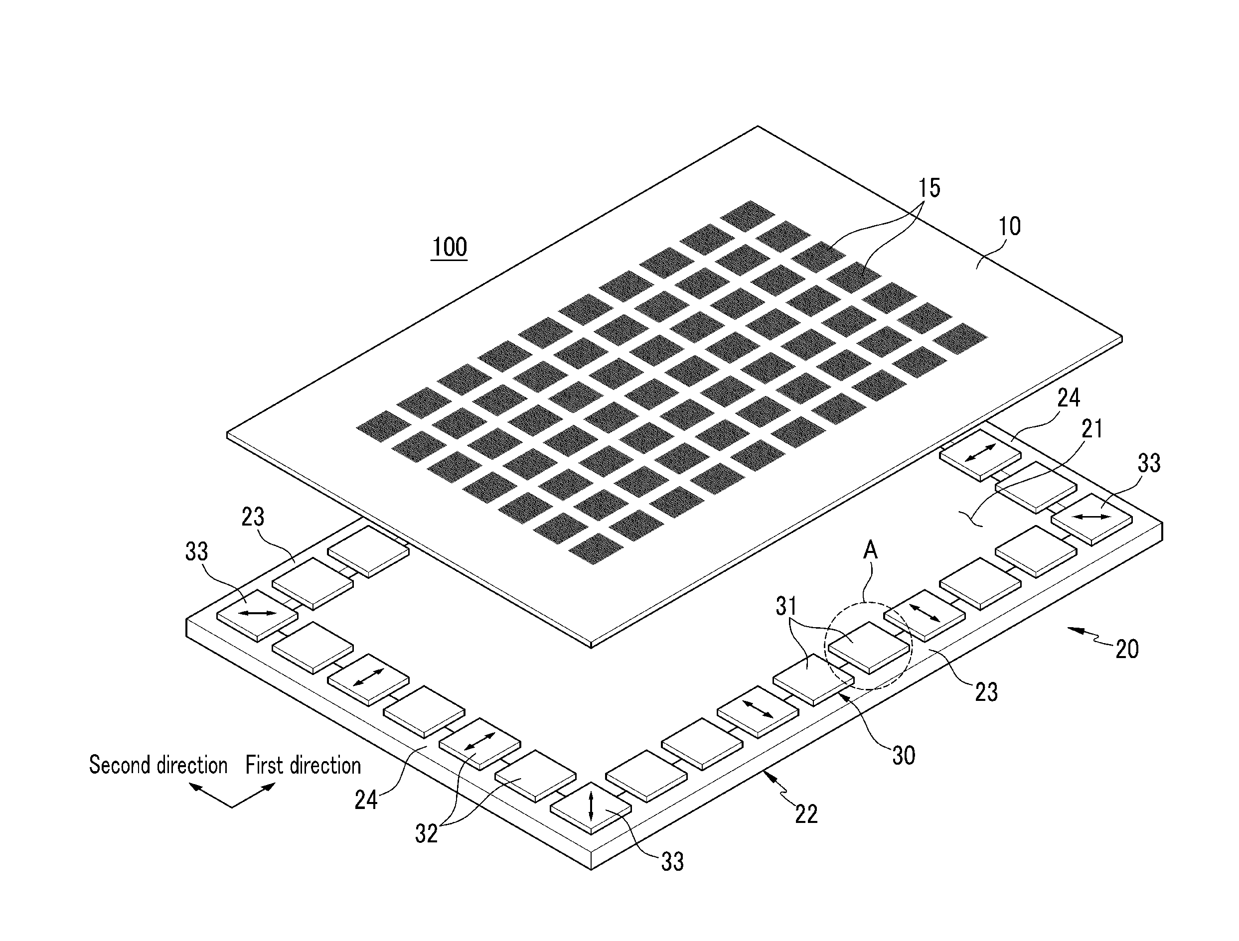
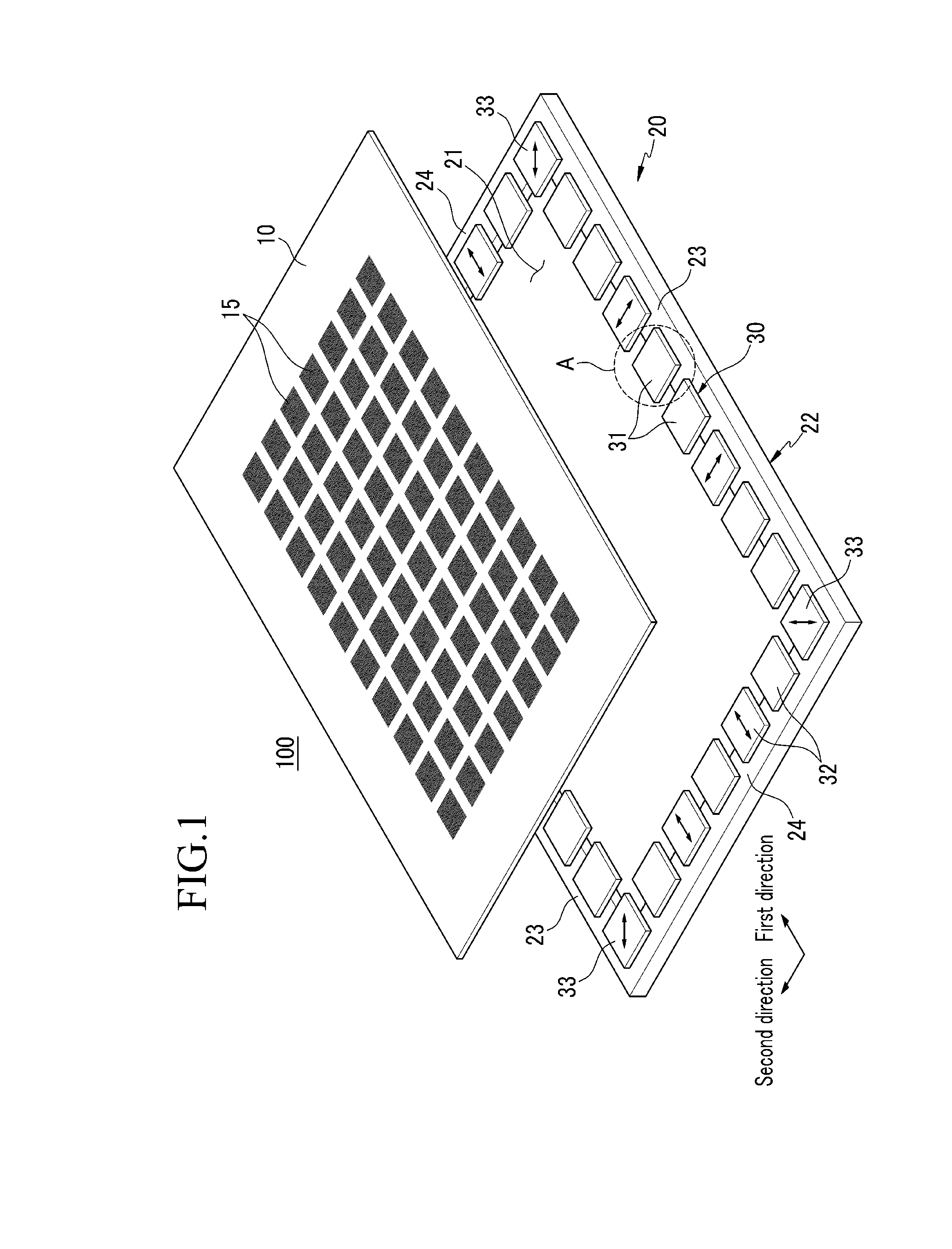
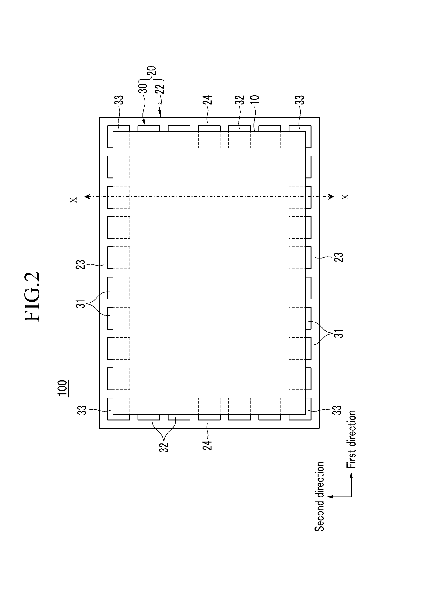
[0050]FIG. 1 and FIG. 2 respectively show an exploded oblique view and a top plan view of a combined state of a mask assembly constructed as a first embodiment according to the principles of the present invention.

[0051]Referring to FIG. 1 and FIG. 2, a mask assembly 100 includes a mask 10 for forming a plurality of pattern openings 15, and a frame 20 for forming an opening 21 for exposing the plurality of pattern openings 15 and supporting the mask 10. The frame 20 includes a frame main body 22 and a plurality of moving members 30 that are installed in the frame main body 22, and the mask 10 is fixed to the moving members 30 through welding.

[0052]The mask 10 is formed as a quadrangular thin metal plate, and forms the plurality of pattern openings 15. The pattern openings 15 are configured with a plurality of fine openings such that a thin film may be deposited therethrough. Therefore, during the deposition process, a deposition material passes through the pattern openings 15 and is ...

second embodiment

[0071]FIG. 5 shows a top plan view of a mask assembly constructed as a second embodiment according to the working principles of the present invention.

[0072]Referring to FIG. 5, the mask assembly 200 according to the second embodiment has a similar configuration to the mask assembly according to the first embodiment except that a plurality of moving members 40 slide in the first direction and the second direction. The same members as in the first embodiment will have the same reference numerals, and differences from the first embodiment will be described hereinafter.

[0073]The plurality of moving members in the first embodiment are classified as the first moving member, the second moving member, and the third moving member depending on the sliding direction, and the plurality of moving members 40 in the second embodiment have a moving controller with the same configuration and they slide not in one direction but in two directions (both the first direction and the second direction).

[00...


PUM

PropertyMeasurementUnit
displacementsaaaaaaaaaa
widthaaaaaaaaaa
tensile forceaaaaaaaaaa

Abstract

A mask assembly includes a frame for forming an opening, and a mask fixed to the frame while a tensile force is applied thereto and forming a plurality of pattern openings. The frame includes a frame main body for forming an opening, and a plurality of moving members installed to be movable in at least one direction on the frame main body. The mask is fixed to the moving members while a tensile force is applied thereto.

Description

CLAIM OF PRIORITY[0001]This application makes reference to, incorporates the same herein, and claims all benefits accruing under 35 U.S.C. §119 from an application earlier filed in the Korean Intellectual Property Office on Dec. 10, 2012 and duly assigned Serial No. 10-2012-0142767.BACKGROUND OF THE INVENTION[0002]1. Field of the Invention[0003]Embodiments of the present invention generally relate to a mask assembly, and more particularly, to a mask assembly used for a thin-film deposition process of an organic emission layer or a metal layer, and a manufacturing method thereof.[0004]2. Description of the Related Art[0005]Flat panel displays, liquid crystal displays (LCD) and organic light emitting diode (OLED) displays are known displays. A flat panel display includes a metal layer of a predetermined pattern, and in a case of an organic light emitting diode (OLED) display, an organic emission layer of a predetermined pattern is formed for every pixel. A deposition method using a ma...

Claims


Application Information

Patent Timeline
Patent Type & Authority Applications(United States)
IPC IPC(8): C23C16/04
CPCC23C16/042C23C14/042Y10T29/49826H10K71/166B05C21/005
Inventor HAN, JEONG-WON
Owner SAMSUNG DISPLAY CO LTD
Why Eureka
Try Eureka