Condensing lens array, and solar cell provided with same

Active Publication Date: 2014-06-12
PANASONIC INTELLECTUAL PROPERTY MANAGEMENT CO LTD
View PDF9 Cites 0 Cited by
  • Summary
  • Abstract
  • Description
  • Claims
  • Application Information

AI Technical Summary

Benefits of technology

[0011]By adopting a concentrating lens array according to an aspect of the present invention and a solar cell including such an array, incoming sunlight is c

Problems solved by technology

Currently, however, the costs of semiconductor materials to make a solar cell and the costs of making a solar cell are so high that the unit cost (i.e., unit energy cost) to generate 1 kW of electric power using a solar cell is approximately several times as high as when electric power

Method used


Image

  • Condensing lens array, and solar cell provided with same
  • Condensing lens array, and solar cell provided with same
  • Condensing lens array, and solar cell provided with same

Examples


embodiment 1

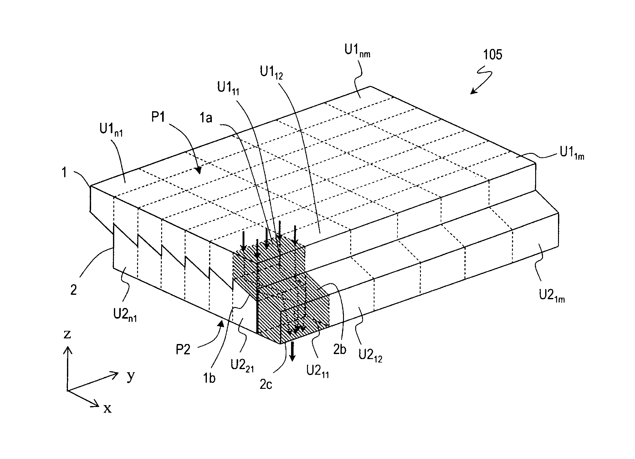
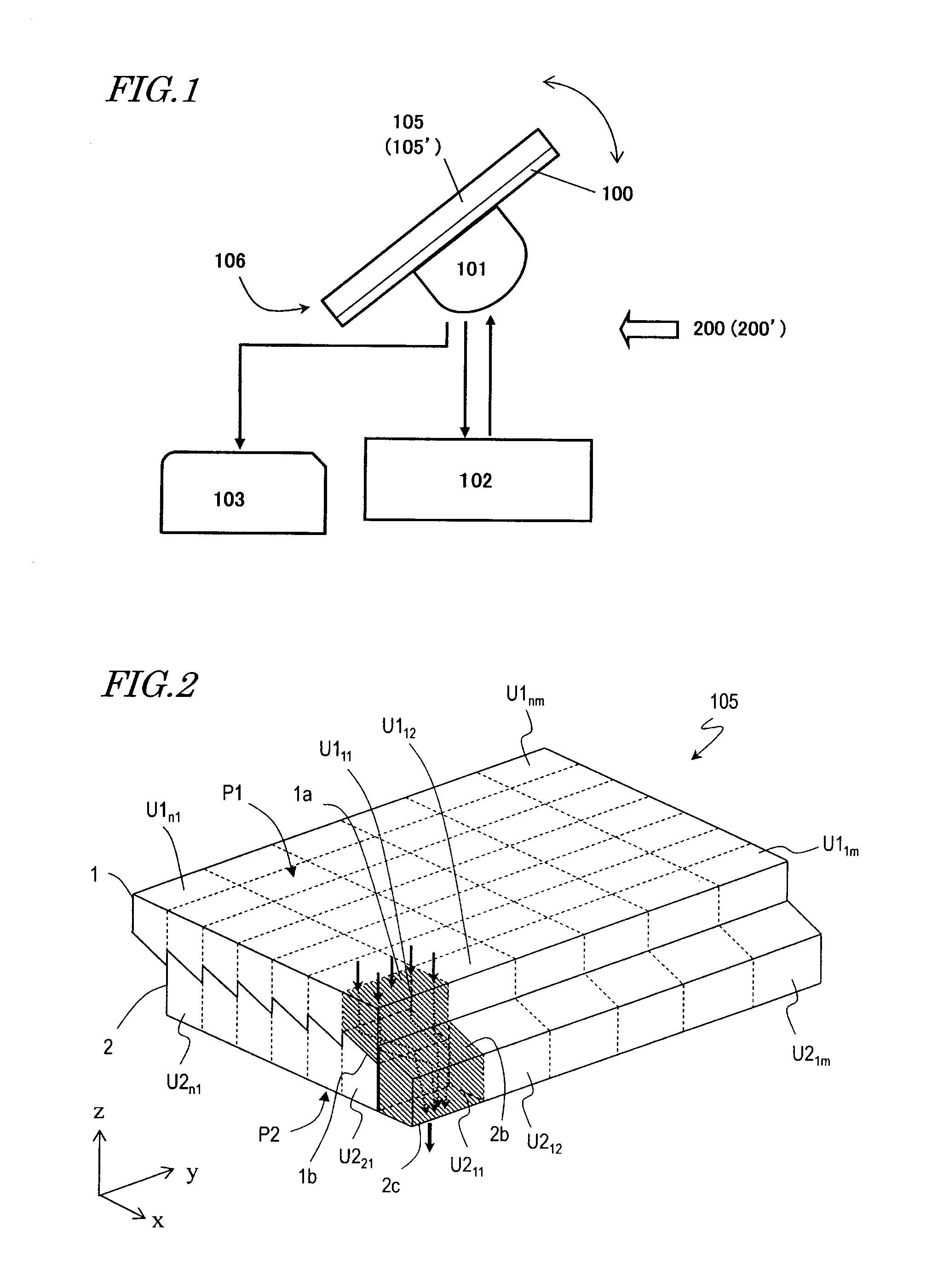
[0051]FIG. 1 illustrates a general configuration for a first embodiment of a sun-tracking solar cell system. The sun-tracking solar cell system 200 shown in FIG. 1 can be used effectively as a relatively large scale solar power generator. This sun-tracking solar cell system 200 includes a concentrating solar cell 106, a rotating mechanism section 101 including a rotating motor to rotate the concentrating solar cell 106, a control section 102 which generates a tracking error of a solar cell substrate 100 with respect to the sun based on a signal supplied from the concentrating solar cell 106 and which sends a rotation signal to the rotating mechanism section 101, and a power storing and transmitting section 103 which either stores or transmits the electrical energy that has been generated by the solar cell substrate 100 through conversion. The entire sun-tracking solar cell system 200 may be formed by known technologies except the concentrating solar cell 106, which includes a concen...

embodiment 2

[0079]Hereinafter, a second embodiment of a concentrating lens array, solar cell including such an array, and sun-tracking solar cell system according to the present invention will be described with reference to the accompanying drawings.

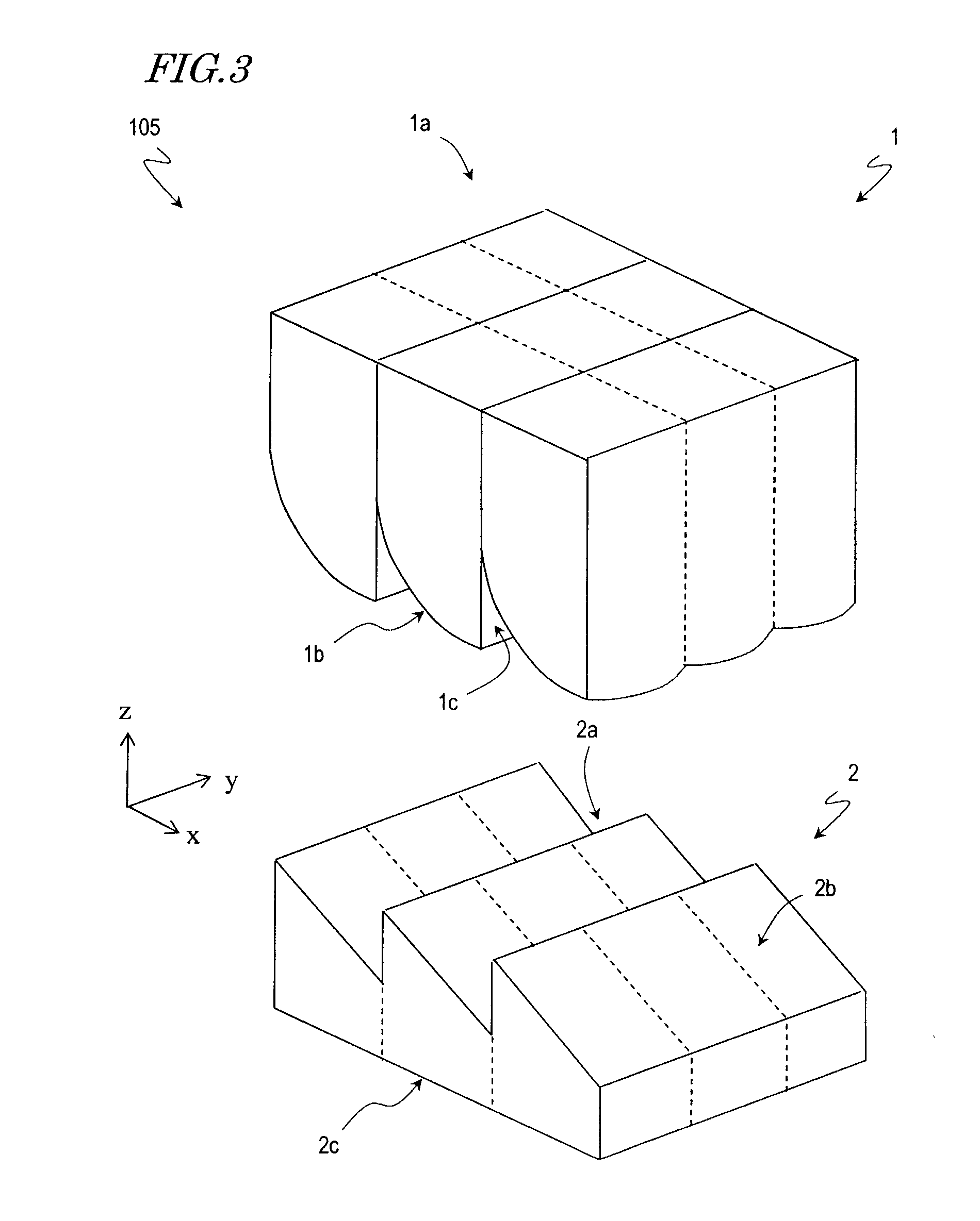
[0080]As shown in FIG. 1, the solar cell system 200′ of this embodiment has the same structure as the solar cell system 200 of the first embodiment except that the system 200′ of this embodiment includes a concentrating lens array 105′ having a different structure from the counterpart of the first embodiment. Specifically, in each unit structure of the concentrating lens array 105′, the second and third surfaces 1b and 2b are cylindrical curved surfaces, which is a major difference from the first embodiment. Thus, the following description will be focused on the structure of the concentrating lens array 105′.

[0081]FIG. 8 is a perspective view schematically illustrating the configuration of the concentrating lens array 105′. In FIG. 8, the concentrat...


PUM


Abstract

A concentrating lens array according to the present disclosure includes a plurality of unit structures arranged at least one-dimensionally. Each unit structure includes: a first surface through which light enters inside of the structure; a second surface which reflects the light that has entered the structure through the first surface; a third surface which reflects the light that has been reflected from the second surface; and a fourth surface which lets the light that has been reflected from the third surface go out of the structure. In each unit structure, the second and third surfaces are located between an incident plane including the first surface and an emitting plane including the fourth surface. At least one of the second and third surfaces reflects the light after having converged the incoming light. When viewed from over the incident plane, the second surface of each unit structure is laid upon the third surface of an adjacent unit structure, and is located closer to the incident plane than the third surface of the adjacent unit structure is.

Description

TECHNICAL FIELD[0001]The present application relates to a concentrating lens array for use in a sun-tracking concentrating solar cell and also relates to a solar cell using such an array.BACKGROUND ART[0002]A solar cell which converts photoelectrically solar energy into electrical energy is a promising power generator. Currently, however, the costs of semiconductor materials to make a solar cell and the costs of making a solar cell are so high that the unit cost (i.e., unit energy cost) to generate 1 kW of electric power using a solar cell is approximately several times as high as when electric power is generated using a thermal power system.[0003]Also, the sun moves from the east to the west. That is why if the photosensitive plane of a solar cell is fixed, the angle of incidence of sunlight onto the solar cell changes as the sun moves. And as the angle of incidence changes, not only the effective light receiving area (which is proportional to cos θ if the angle formed between a no...

Claims


Application Information

Patent Timeline
IPC IPC(8): H01L31/052G02B3/00F24S23/00F24S23/30
CPCG02B3/0037H01L31/0524F24S23/00F24S23/30G02B3/005G02B3/0056G02B5/045G02B19/0028G02B19/0042H01L31/0543H01L31/0547H02S20/32Y02E10/44Y02E10/52
Inventor NISHIWAKI, SEIJI
Owner PANASONIC INTELLECTUAL PROPERTY MANAGEMENT CO LTD
Why Eureka
Try Eureka