Single stage switching power amplifier with bidirectional energy flow

a power amplifier and single-stage technology, applied in the direction of amplifiers with semiconductor devices/discharge tubes, dc isolation amplifiers, transmissions, etc., can solve the problems of lowering system efficiency, inductor core losses, and a number of design deficiencies, so as to achieve the effect of increasing system efficiency

Active Publication Date: 2014-06-12
GUANGDONG RUI DING ELECTRICAL TECH
View PDF5 Cites 6 Cited by
  • Summary
  • Abstract
  • Description
  • Claims
  • Application Information

AI Technical Summary

Benefits of technology

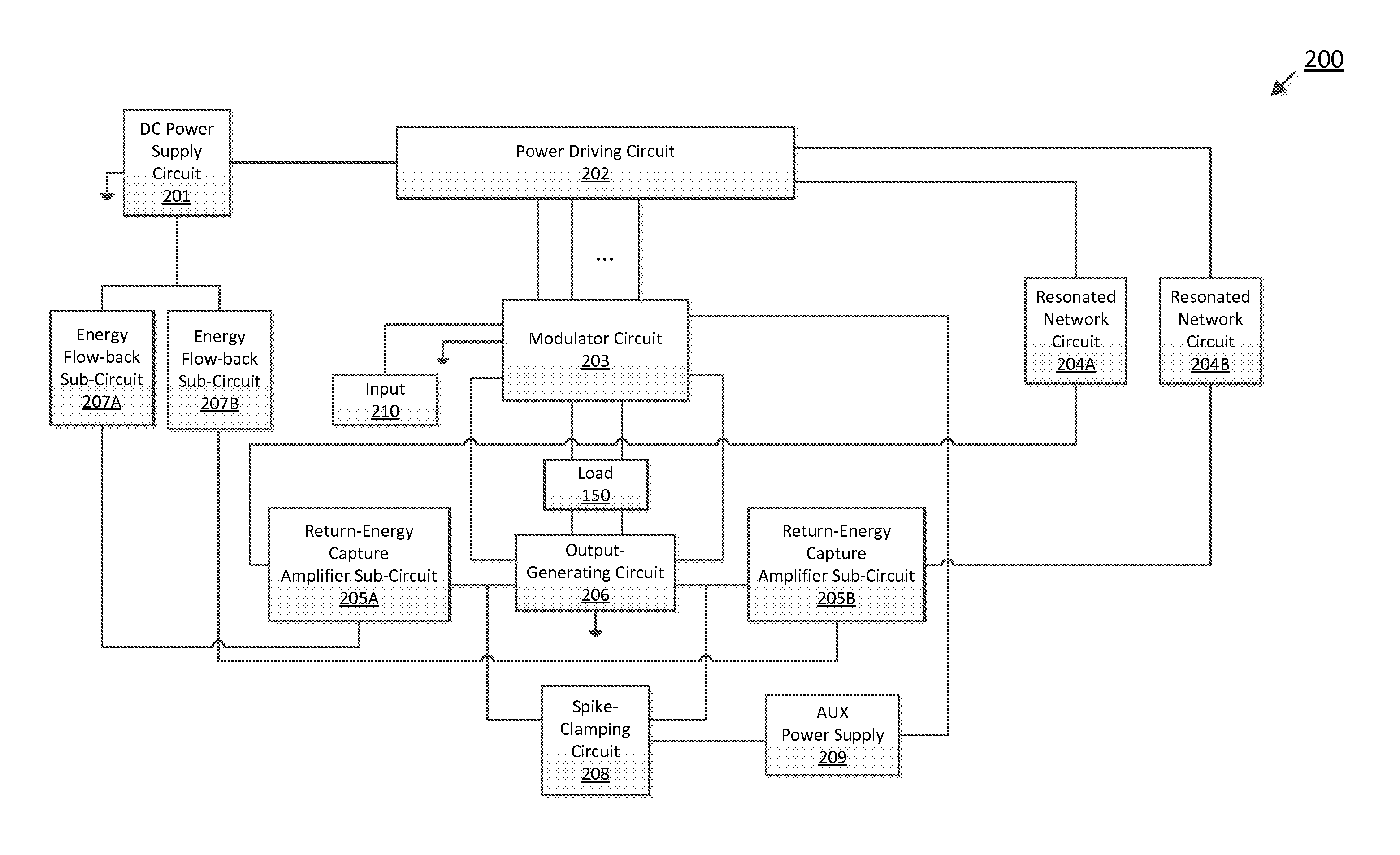
[0021]In one aspect, the present disclosure provides a single stage switching power amplifier that is designed in such a manner that the amplifier can afford to use a pair of individual inductors, rather than is forced to use a pair of tightly magnetically coupled inductors, in a pair of low pass filters situated across a load.
[0023]In yet another aspect, the present disclosure provides a single stage switching power amplifier comprising a spike-clamping circuit, which clamps voltage spikes at a pair of output nodes coupled to a respective pair of low pass filters situated across a load for providing an amplified differential output signal, stores the clamped energy, and recirculates the stored energy to power other one or more associated circuitries via, for example, an Aux power supply, thereby further increasing system efficiency.

Problems solved by technology

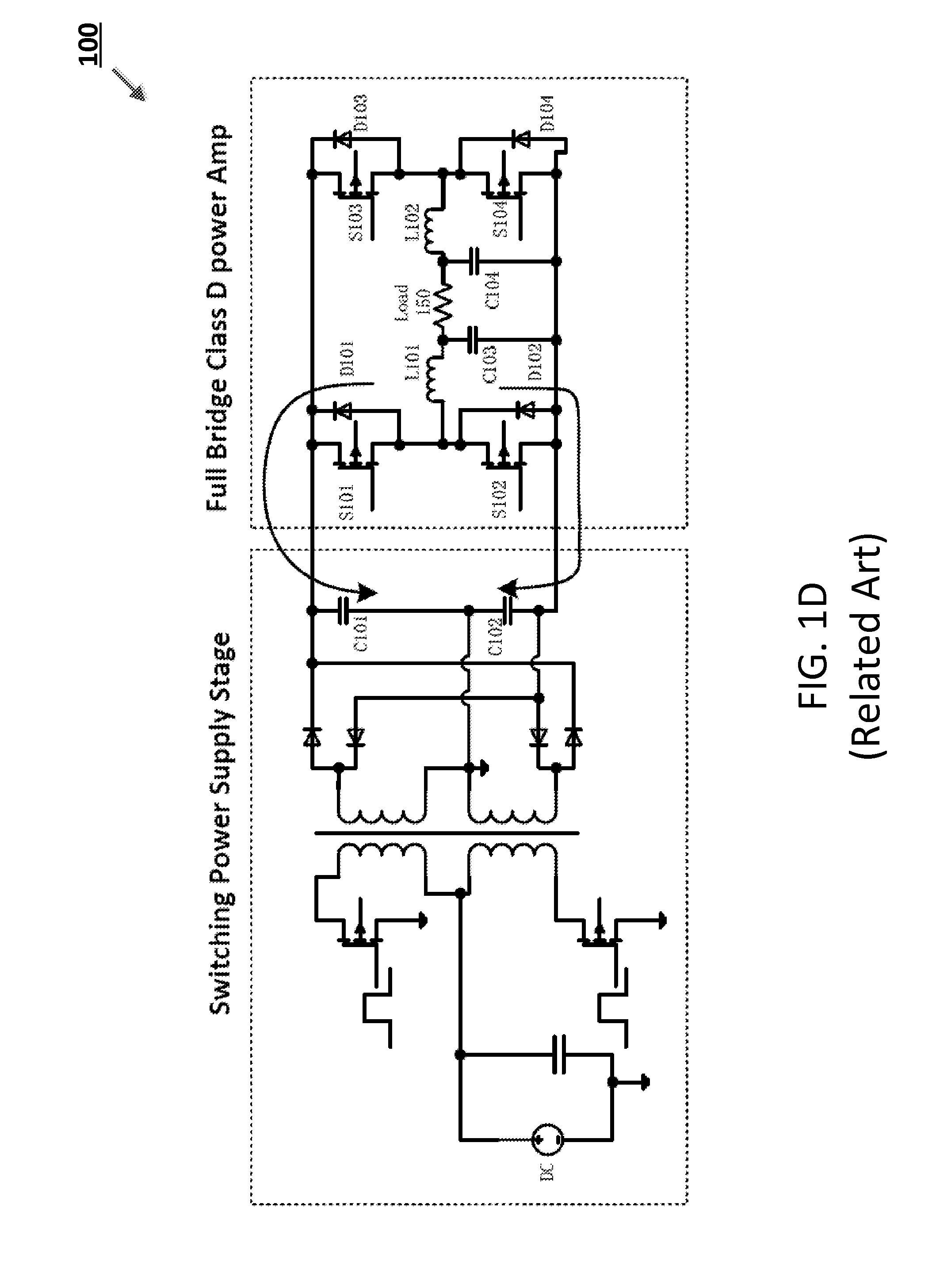
At each stage, such a two-stage or multi-stage power amplifier incurs power losses, resulting in lowering the system efficiency.
However, the '309 amplifier suffers from a number of design deficiencies, primarily due to its failure to adequately address new issues arising from combining the “power-supplying” stage and the “power-amplifying” stage into a single stage.
The high-frequency ripple current can cause inductor core losses, since, with today's technology, very few (if not no) magnetic material (of which any inductor is made) can sustain such an extreme high-frequency ripple current.
With today's technology, however, it is practically impossible to find capacitors that can handle this amount of ripple current.
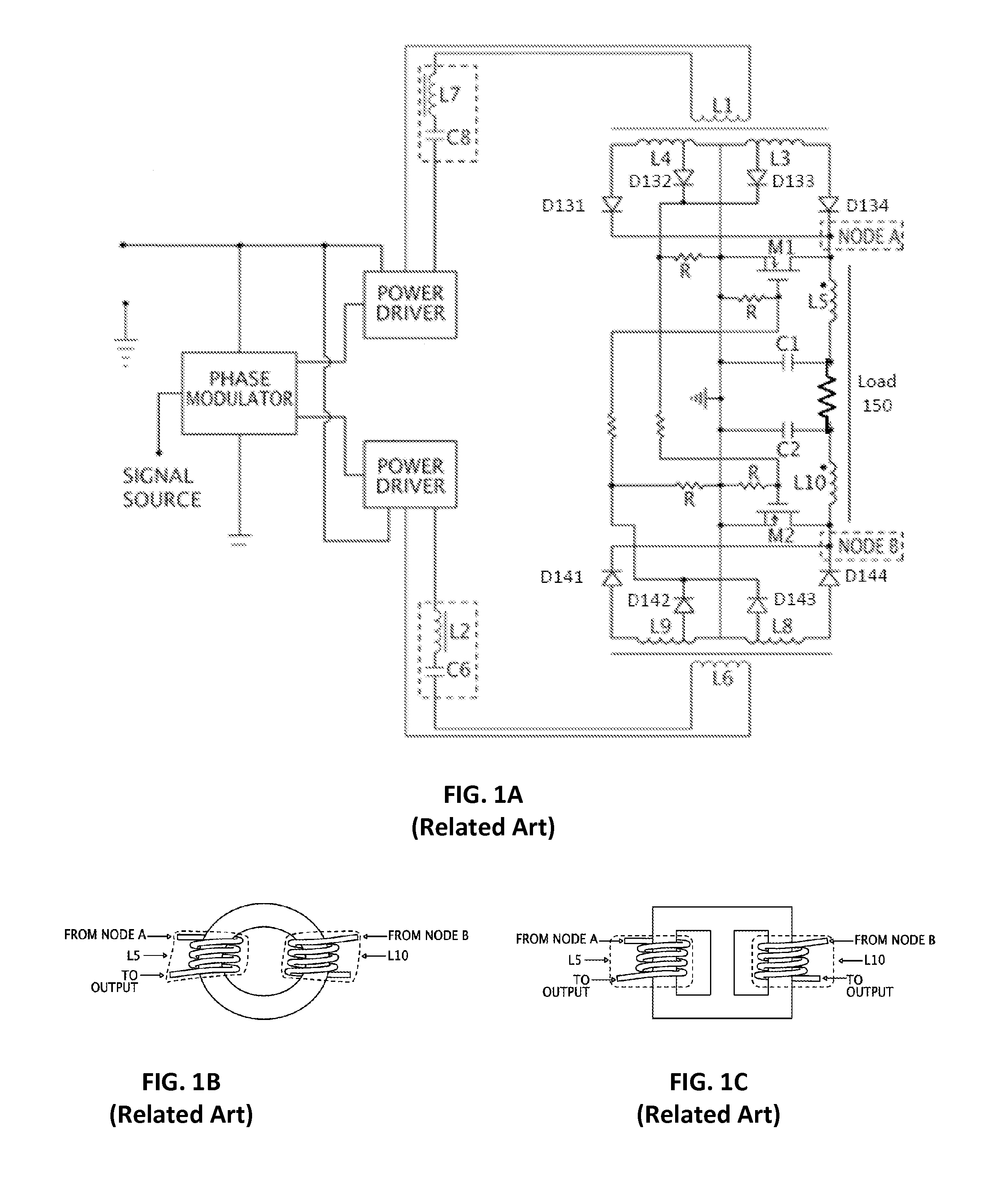
Furthermore, with the tightly coupled inductors L5 and L10, there also comes the leakage inductance thereof, which causes high-magnitude voltage spikes on both nodes A and B of the '309 amplifier.
Such voltage spikes, even if controlled with a clamping circuit, will cause lots of energy wasted, thereby reducing the system efficiency.
Thus, for the '309 amplifier, requiring a highly magnetically coupled pair of inductors L5 and L10 is a design deficiency.
The second design deficiency of the '309 power amplifier is that the '309 power amplifier can only drive a resistive type of load, but cannot drive a pure inductive type of load.
In particular, under its design, the '309 amplifier does not provide storage as well as a return path for excess energy released (returned) from the inductive load.
As a result, the '309 amplifier cannot drive a pure inductive type of load, such as a motor.
This limitation severely restricts the usability of the '309 amplifier, and thus is also a design deficiency.
The third design deficiency of the '309 power amplifier is that its configuration in connection with MOSFET switches M1 and M2 cannot reliably ensure that only one of M1 and M2, but not both, is conducting at any moment.
This is a condition that can cause the secondary windings of the two switching transformers shorted and as a result render the '309 amplifier inoperable.
The aforementioned design deficiencies of the '309 amplifier are primarily due to its failure to address issues arising from combining the aforementioned power-supplying stage and the power-amplifying stage into a single stage.
These issues are usually not applicable to a conventional two-stage switching power amplifier.
As a result, new issues—such as not readily having a path for high-frequency inductor current when one switch is turned off, not readily having storage as well as a current circulation path for energy returned from a pure inductive load, and not readily having much flexibility in relative timings between switches—inevitably arise.
As to the design of the '309 amplifier, these new issues are simply not adequately addressed, thus resulting in the aforementioned design deficiencies.

Method used


Image

  • Single stage switching power amplifier with bidirectional energy flow
  • Single stage switching power amplifier with bidirectional energy flow
  • Single stage switching power amplifier with bidirectional energy flow

Examples


Embodiment Construction

[0036]In the following detailed description of exemplary embodiments of the disclosure, specific exemplary embodiments in which the disclosure may be practiced are described in sufficient detail to enable those skilled in the art to practice the disclosed embodiments. For example, specific details such as specific method orders, structures, elements, and connections have been presented herein. However, it is to be understood that the specific details presented need not be utilized to practice embodiments of the present disclosure. The following detailed description is, therefore, not to be taken in a limiting sense, and the scope of the present disclosure is defined by the appended claims and equivalents thereof.

[0037]References within the specification to “one embodiment,”“an embodiment,”“embodiments”, or “one or more embodiments” are intended to indicate that a particular feature, structure, or characteristic described in connection with the embodiment is included in at least one ...


PUM


Abstract

A switching amplifier realizes bidirectional energy flow and combines switching and power amplification into one single stage so as to increase system efficiency. The modulator circuit of the amplifier receives and modulates an input signal, and generates and outputs modulated driver signals, which are used by the power driver circuit to generate signals to drive switching transformers of an amplifier circuit of the amplifier, and control signals, which are used to control an output generator circuit so as to allow individual inductors across the load by enabling current flowing through the load to have a path to ground. The amplifier circuit comprises switching transformers as well as circuitries configured to capture energy returned from the load and enable the captured energy to flow back to a power supply circuit of the amplifier through an energy flow-back circuit of the amplifier.

Description

CROSS-REFERENCE TO RELATED APPLICATION[0001]This application claims the benefit under 35 U.S.C. §119(e) of Provisional Patent Application No. 61 / 732,324, filed Dec. 1, 2012, the entire disclosure of which is hereby incorporated by reference.BACKGROUND[0002]1. Technical Field[0003]The present disclosure generally relates to switching power amplifier, and more particularly to single stage switching power amplifier which, among other advantages, achieve bidirectional energy flow.[0004]2. Description of the Related Art[0005]A conventional switching power amplifier, such as a class-D power amplifier, usually undergoes at least two stages—namely, the first stage of generating needed power supply (hereinafter referred to as “the power-supplying stage”) and the second stage of applying the generated power supply to amplify an input signal with one or more switching configurations (hereinafter referred to as “the power-amplifying stage”)—before producing an output signal across a load couple...

Claims


Application Information

Patent Timeline
Patent Type & Authority Applications(United States)
IPC IPC(8): H03F3/217H02M1/00
CPCH03F1/02H03F3/24H03F3/2171H02M1/34H04B2001/045H03F3/217H02M1/0038H03F2200/171H03F2200/273H03F2200/66
Inventor CHEN, XUE JIAN
Owner GUANGDONG RUI DING ELECTRICAL TECH
Why Eureka
Try Eureka